CRANKSHAFT/RODS/PISTONS 6
CONNECTING ROD BIG END BEARING
SELECTION/CRANKPIN WEAR CHECK
1.
Measure the bearing and crankpin clearance as
follows.
NOTE:
•
Do not turn the connecting rod and crankshaft
during the clearance measurement as this will
damage the plastigauge.
The crankpin
clearances are measured using 'Plastigauge'
(Triumph part number 3880150-T0301).
2.
Remove the big end cap from the journal to be
checked.
3.
Wipe the exposed areas of the crankpin, and the
bearing face inside the cap.
4.
Apply a thin smear of grease to the journal and a
small quantity of silicone release agent to the
bearing.
5.
Trim a length of the plastigauge to fit across the
journal. Fit the strip to the journal using the
grease to hold the plastigauge in place.
6.
Lubricate the threads of the bolt and the face of
the nut with molybdenum disulphide grease. Refit
the bearing and cap and tighten the big end nuts
as described earlier.
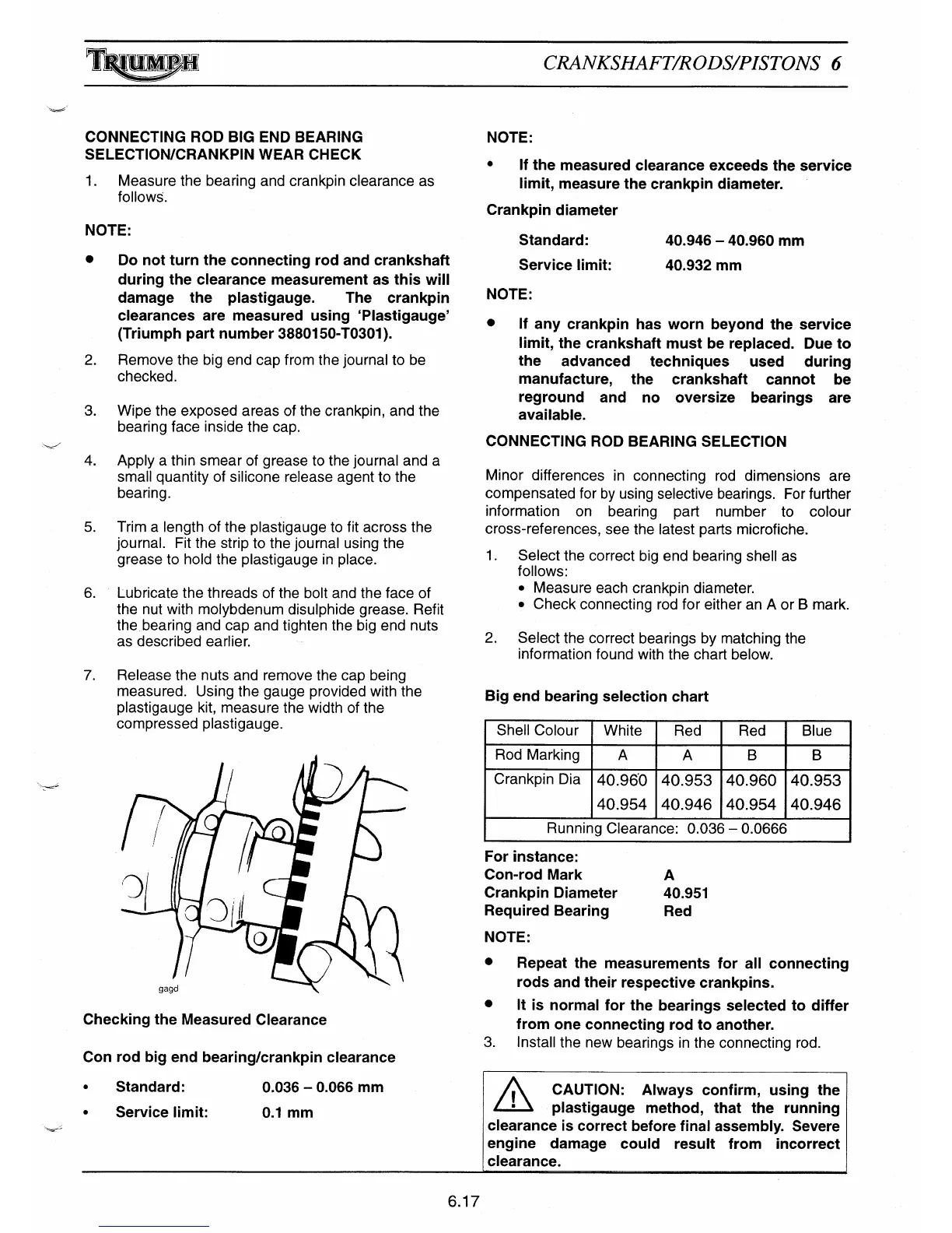
7.
Release the nuts and remove the cap being
measured. Using the gauge provided with the
plastigauge kit, measure the width of the
compressed plastigauge.
Checking the Measured Clearance
Con rod big end bearing/crankpin clearance
NOTE:
•
If the measured clearance exceeds the service
li
mit, measure the crankpin diameter.
Crankpin diameter
Standard:
40.946 — 40.960 mm
Service limit:
40.932 mm
NOTE:
•
If any crankpin has worn beyond the service
li
mit, the crankshaft must be replaced. Due to
the advanced techniques used during
manufacture, the crankshaft cannot be
reground and no oversize bearings are
available.
CONNECTING ROD BEARING SELECTION
Minor differences in connecting rod dimensions are
compensated for by using selective bearings. For further
information on bearing part number to colour
cross-references, see the latest parts microfiche.
1.
Select the correct big end bearing shell as
follows:
• Measure each crankpin diameter.
• Check connecting rod for either an A or B mark.
2.
Select the correct bearings by matching the
information found with the chart below.
Big end bearing selection chart
Shell Colour
White
Red Red
Blue
Rod Marking
A
A
B
B
Crankpin Dia
40.960
40.954
40.953
40.946
40.960
40.954
40.953
40.946
Running Clearance: 0.036 — 0.0666
For instance:
Con-rod Mark
A
Crankpin Diameter
40.951
Required Bearing
Red
NOTE:
•
Repeat the measurements for all connecting
rods and their respective crankpins.
•
It is normal for the bearings selected to differ
from one connecting rod to another.
3.
Install the new bearings in the connecting rod.
•
Standard:
0.036 — 0.066 mm
CAUTION: Always confirm, using the
method, that the runnin
•
Service limit:
0.1 mm
plastigauge
running
clearance is correct before final assembly. Severe
engine damage could result from incorrect
clearance.
6.17