Revision C – January 2023
CDS2000 Page | 11
updated every second and if the flowrate is out of range, the “RATE” descriptor above
the bar graph will turn red and flash,
and the red System Alarm LED will
flash.
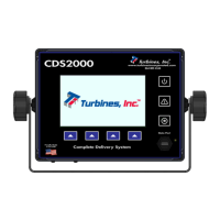
Accumulative Totalizer: The accumulative
or grand total is in the middle left of the
CDS2000 display and reads “TOTALIZER”
followed by the unit of measure selected in
the Metrology Configuration menu. This
totalizer is “slaved” to the Delivery Totalizer
and increments in the same engineering
units. The accumulative or grand total is
privilege password protected and can only be
reset by factory personnel. If the engineering
unit of the total is changed, the displayed
accumulated total will be converted automatically to the equivalent total in the new engineering
unit. The accumulative total is limited to 10 digits. Once 9,999,999,999 is exceeded, the digits will
turn red and continue counting.
K-Factor Information: The displayed K-factor information has a dual purpose. If the linearizer is
inactive, the displayed K-factor represents the latest K-factor entered into the setup menu. If the
linearizer is active, the K-factor information is replaced with the word “LINEARIZER.” The
instantaneous calculated linearized K-factor based on flow rate is available on the Detail Display.
Delivery Total: The delivery total, located in the bottom left corner of the CDS2000 display,
represents the cumulated total since the last Reset action. (Refer to RESET softkey Page 9) The
delivery total is the total pulses generated divided by the K-factor and corrected for temperature if
compensation is activated. If the engineering unit of measure is changed the displayed delivery
total will be automatically reset to zero. Once 99,999,999 is exceeded, the digits will turn red and
continue counting.
Directly above the Delivery Totalizer the engineering units of measure and delivery conditions
are displayed. If the temperature compensator is activated and the delivery temperature is within
range, the engineering unit of measure will be displayed with “CORRECTED @ NBP.” The total
will be corrected to metered conditions (at the measured temperature). If the delivery temperature
is out of range, “@ DEFAULT TEMP” will be displayed and the delivery total will be corrected at
the warmest delivery temperature for that product. To view the uncompensated total, press the
DETAILS softkey. If the temperature compensator function is turned “Off”, “UNCOMPENSATED”
will be displayed above the delivery total and the TCF will be 1.000 (volumetric).
Programmable settings within
Metrology Selections & UOM can allow the totalizer to continue to
count in the event of an alarm. Count During Temp Sensor Fail, Count During Temp Out of
Range, and Count During High Flow can be programmed either “YES” or “NO”. More information
can be found on page 20: Metrology Configuration -> Metrology Selections -> Compensation.
AlarmsDisplay(AlarmIcons)
The Alarms Display, accesses the following sub-menus:
Current alarms
Delivery alarms
Pressing the Alarms softkey will display alarm conditions. The System Alarm Log can be found in
the “System Settings” tab in the Setup Menu and maintains a history of alarms (Alarm Log). The
log can be accessed with Privileged or User Passwords.
Thermometer Icon: The thermometer icon is visible if the temperature compensator is
activated, and the delivery temperature is out of range for longer than the intermittent
temperature tolerance timer (see Setup Menu page 19). This icon is also visible if
RTD1 or RTD2 is open or shorted, or if the 4-20 mA temperature input is out of range.
The thermometer icon will be displayed, and the delivery total will be corrected at the
warmest delivery temperature for that product.