Revision C – January 2023
CDS2000 Page | 12
Flow Range (Water Valve) Icon: The FLow Range or Water Valve icon is visible if
the flow rate is out of the calibrated range for the flowmeter. This icon also appears
if dual coil is enabled, and reverse flow is detected or if there is a power failure
during a delivery. It is possible that the water valve icon will illuminate momentarily
as the flowmeter accelerates from no flow to a flow rate that is within the calibrated
range for that flowmeter. Please Note: flow rates above the maximum rate are considered a
delivery alarm.
Pressure Gauge Icon (LPA indicator):
The Pressure Gauge Icon is
displayed when the delivery pump is disabled due to a low-pressure alarm. If the
cool down timer is enabled and still counting down, then the icon appears and the
pump is off. If cavitation detection is enabled or the digital differential pressure is
enabled, then the icon is on and power to the pump has been interrupted.
System Maintenance Icon:
A system maintenance (wrench and
screwdriver) icon indicates that a system, pump or turbine maintenance
condition exists. Maintenance alarms are summarized under “Current Alarms”
(see Alarms Display on page 11). An example of a maintenance alarm would
be “Turbine Maintenance Due.” Please Note: system maintenance due does not affect normal
operation.
Pickup Coil Icon:
A pickup coil icon indicates there is a problem with one of the
enabled (A or B) pickup coils. If the pickup coil is open or shorted, then this alarm
icon is visible and the corresponding alarm will be active in the alarm menu. If dual
coil mode is enabled, this icon is also visible if there is a dual coil error (pulse
counts between coil A & B do not match) or reverse flow is detected.
Gas Pump Icon:
The Gas Pump Icon indicates a problem with the pump. It
is visible when the pump is disabled due to the cool down timer or cavitation
has been detected due to low pump pressure. There is a future option
available where a digital input signal can disable the pump (such as from a
differential pressure switch) but this feature is generally not used. Additional
System Settings -> Pump Settings can be found on page 23.
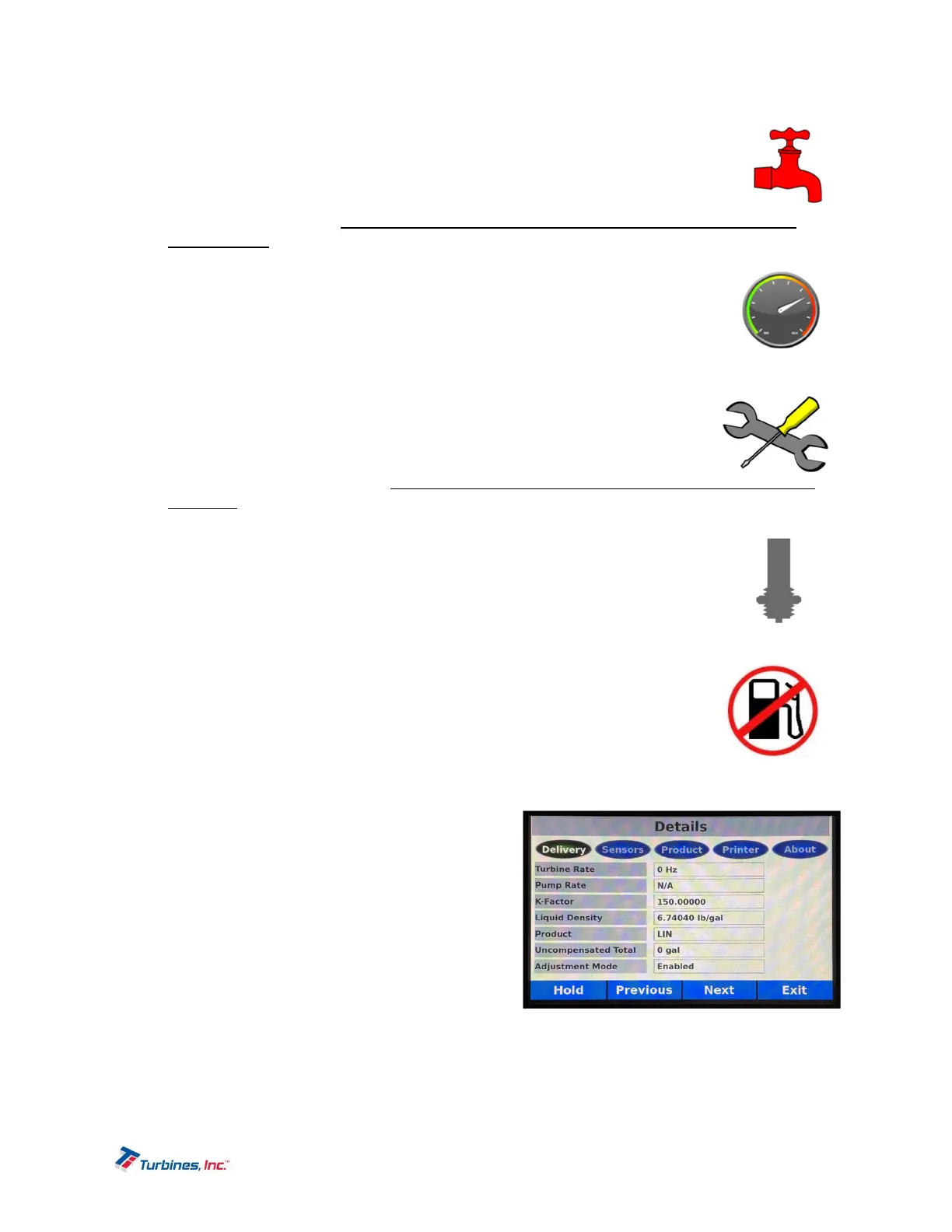
DetailsDisplay
The Details Display, accesses the following sub-menus:
Delivery
Sensors
Product
Printer
About
The Details Display shows additional information
regarding the operating conditions of the system. Details
are broken into five different sections: Delivery,
Sensors, Products, Printer, and About.