Revision C – January 2023
CDS2000 Page | 7
Optional pump control and protection based on pump discharge or differential pressure.
Built-in self-test system of diagnostics.
Comprehensive internal warning and error reporting system.
Pump and turbine maintenance timers.
Non-resettable “Grand” totalizer.
RS-232, USB and Bluetooth communications are available.
Level 3 Audit trail for all sealable meteorological parameters.
Password protected configuration and calibration parameters.
Overview
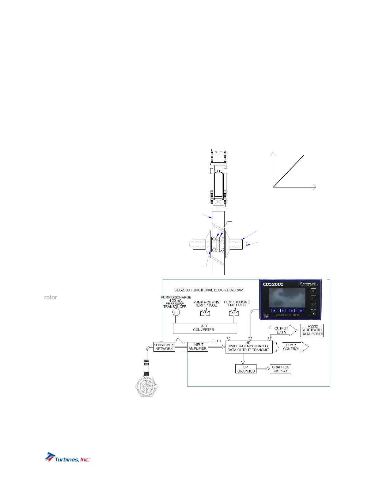
When introduced to flow the turbine flowmeter generates an AC sinewave signal within the pickup coil
located directly above the turbine’s rotor. The signal of the pickup coil is amplified, divided, corrected, and
displayed by the CDS2000. The displayed total
is corrected for temperature by sensing the
resistance of the RTD temperature probe.
Delivery information, consisting of 17 selectable
parameters, is transmitted via Bluetooth or
RS232 communications depending on which
data collection device or printer is selected.
Historical delivery data in internally captured
and can be offloaded via a built-in USB
interface. This unique integrated system
provides the end user a configurable, compact
total delivery system.
TheoryofOperation
The TI turbine flowmeter is a velocity
measurement device that measures fluid
velocity and volume with one moving
component, the rotor. The
momentum of the flowing
fluid engages the low mass
rotor
resulting in the rotor
rotating at an angular
velocity that is proportional
to the fluid velocity. The
rotor’s rotation generates an
AC sinewave signal in the
pickup coil. TI turbine
flowmeters are linear
devices therefore the signal
output frequency is
proportional to the flowrate
within the designed flow
range. Another benefit of a
linear turbine meter is its K-
factor, the number of pulses
generated per unit volume (gallons, pounds etc.) is consistent over the entire flow range. The total
number of pulses generated is directly related to the total volume. The displayed total in the desired
engineering unit is acquired by dividing the total pulses by the K-factor. Because product density is
influenced by fluid temperature, volumetric flow meters require temperature to be measured and
SIGNAL AMPLITUDE
Q
0
MAX
FL OW
MI N
5000
mV pp
Bearings
Cone
Plat form
Ro t o
Sha ft
Co n e
Faraday - voltage induced from interruption of a magnetic
fie ld by p as s ag e o f a fe r r ou s ob jec t thr ou gh t he
fie ld is pr op or tio nal to v el oc ity of th e pas s in g objec t.