System Description IO-Link
System architecture
10
Hans Turck GmbH & Co. KG | T +49 208 4952-0 | F +49 208 4952-264 | more@turck.com | www.turck.com
4 System Description IO-Link
IO-Link is a fieldbus independent communication interface for sensors and actuators. Signals
and energy can be exchanged between any networks, fieldbuses and backplane buses via a di-
gital, serial point-to-point connection.
Each IO-Link system consists of an IO-Link master and an IO-Link device (e.g. sensor, I/O hub,
valve block). An IO-Link master is provided with at least one IO-Link port (channel). One IO-Link
device can be connected to each port. The system components are interconnected according
to the port specification via unshielded 3-wire or 5-wire standard cables.
The IO-Link technology is described in the “IO-Link Interface and System Specification” and IEC
61131-9. IO-Link capable devices comply either with specification V1.0 or specification V1.1.
The properties, functions and parameters of the IO-Link device are represented in an electronic
device description (IODD). The IODDs for Turck devices can be downloaded via the Turck Soft-
ware Manager and can also be obtained free of charge from www.turck.com . The IODDs of all
devices have the same structure and contain the following information for system integration
n Communication properties
n Device parameters with value range and default value
n Identification, process and diagnostic data
n Device data
n Text description
n Picture of the device
n Logo of the manufacturer
The structure of the IODD is defined by the IO-Link specification and is the same for all IO-Link
devices. The IODD is based on indexes. The communication properties, device parameters,
identification, process, diagnostic and device data are assigned to fixed indexes in the IODD, via
which the parameters can be controlled. Some indexes are further divided by sub indexes.
4.1 Features
n Point-to-point connection (max. cable length: 20 m)
n Unshielded 3-wire or 5-wire standard cables
n Cyclical process data transmission
n Acyclical data transmission, e.g. device data and events
n Communication between IO-Link master and IO-Link device possible in three transmission
rates
n Parallel exchange of device data without influencing the process data
n Communication via 24 V pulse modulation, standard UART protocol
4.2 System architecture
At least one IO-Link master and one IO-Link device (e.g. sensor or actuator) are required for IO-
Link communication. IO-Link master and IO-Link device are interconnected via an unshielded 3-
wire or 5-wire standard cable. The setting can be carried out with a configuration tool or via the
fieldbus level.
The IO-Link master establishes the connection between IO-Link device and the higher-level
control system. An IO-Link master can have several IO-Link ports. Only one IO-Link device can
be connected to each port.
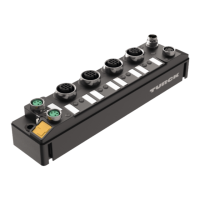
IO-Link hubs also make it possible to integrate devices without an IO-Link output in automation
systems via IO-Link.
Standard tools and functions are provided for the integration, commissioning and configura-
tion of the IO-Link communication.

 Loading...