Connecting
Connecting IO-Link devices and digital sensors
26
Hans Turck GmbH & Co. KG | T +49 208 4952-0 | F +49 208 4952-264 | more@turck.com | www.turck.com
7.2.1 Supply concept
The TBEN-S2-4IOL is supplied via two separate voltages V1 and V2.
V1 = supply of the module electronics and the respective slots
V2 = supply of the respective slots
Fig.24: Power supply of TBEN-S2-4IOL
7.3 Connecting IO-Link devices and digital sensors
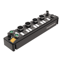
The device has four eight M12 female connectors for connecting IO-Link devices and digital
sensors and actuators. The maximum tightening torque is 0.8 Nm.
NOTICE
Wrong supply of IO-Link devices
Damage to the device electronics
Only supply IO-Link devices with the voltage provided at the M12 connectors.
Connect the sensors and actuators to the device according to the pin assignment.
4
1
3
2
5
v
1 = V
aux
2
2 = DXP
3 = GND V2
4 = C/Q
5 = n.c.
C1...C4
Fig.25: Pin assignment C0…C3
Pin Meaning
Pin 1 VAUX2, not short-circuit proof
Pin 2 Digital in- or output (DXP)
Pin 3 Ground V2
Pin 4 IO-Link or digital input
Pin 5 Not connected

 Loading...