UHP SCPC MODEM
USER MANUAL, v3.2
© ROMANTIS 2015 16 www.uhp.net
Up and Down buttons allow adjusting the level manually with 1dB step. When adjusting the transmission level by
Up and Down buttons such new settings will be applied automatically without clicking the “Apply” button.
Fractional values (e.g. 25.8 dB) should be set manually.
2.3.4 TLC Settings
This section describes configuration of the automatic transmission level control of the Station. To run TLC
algorithm the maximum Station’s transmission level (Max TLC TX level) should be set. This setting is determined
either on the basis of the operator requirements for maximum permitted signal levels (max EIRP of the Station) or
on the basis of 1dB compression point. The latter is the point where the BUC amplifier goes into compression and
becomes non-linear. The value should usually be at least 1 dB lower than the transmitter compression power.
In this section the following parameters are configured:
• The maximum transmission level for own signal – Max TLC TX level;
• This parameter is being determined either on the base of the satellite operator requirements to the
permissible level of the relay signal (EIRP stations), or based on the maximum (maximum linear)
station transmission power ;
• The parameters providing the exchange safety of the information about routers transmission and
receive levels – SCPC TLC protocol settings.
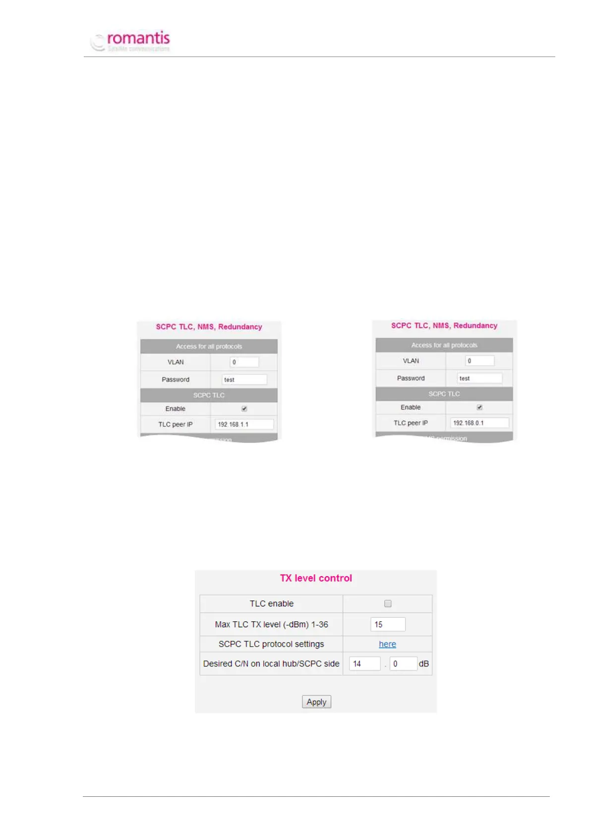
Figure 13 TLC Security Settings for Station-1
Figure 14 TLC Security Settings for Station-2
The TLC Security setting form specifies the IP-address of remote Station and the respective password. The
password will be used to secure Information exchanges of current receive levels and power control messages.
Once respective form is configured it should be applied to take effect.
Desired C/N receive level on the remote Station (Desired C/N on local hub/SCPC side) should be set using TX level
control form. This level should ensure proper quality of receive for the defined MODCOD. It is recommended using
C/N values defined in the UHP specifications plus some (0.4-0.9 dB) margin.
Figure 15 Transmission Level Control configuration
TLC enable check-box activates TLC machoism. After entering the corresponding parameters it is necessary to
press Apply.