UHP SCPC MODEM
USER MANUAL, v3.2
© ROMANTIS 2015 30 www.uhp.net
going down again. Choose the maximum C/N level and fix the fittings responsible for elevation angle
adjustment.
3. Polarization Adjustments;
Release the fittings responsible for antenna feed system adjustment. Slowly turn the antenna clockwise
and monitor the C/N value on the screen. If the level is falling slowly turn the antenna down until the level
is going down again. Choose the maximum C/N level and fix the fittings.
4. Check Antenna Degree of Resilience;
Push the antenna carefully with hands and try to shift it by azimuth, tilt angle and polarization angle
tracking the C/N value. The applied pressure should be at the level of possible wind loads that the
antenna system will experience. Once the force is removed from the antenna the C/N value should return
to the maximum recorded during the fine tuning of the antenna.
If required, repeat stages 1-4.
5.2 Cross Polarization Test
5.2.1 Preparation for Measurement
After pointing the antenna to the satellite measure the cross-polarization isolation level. The preparation for
measurement requires:
1. Prepare the UHP router for the measurement:
Go to Profiles section in the Menu of commands. A table of profiles will be displayed on the Control panel;
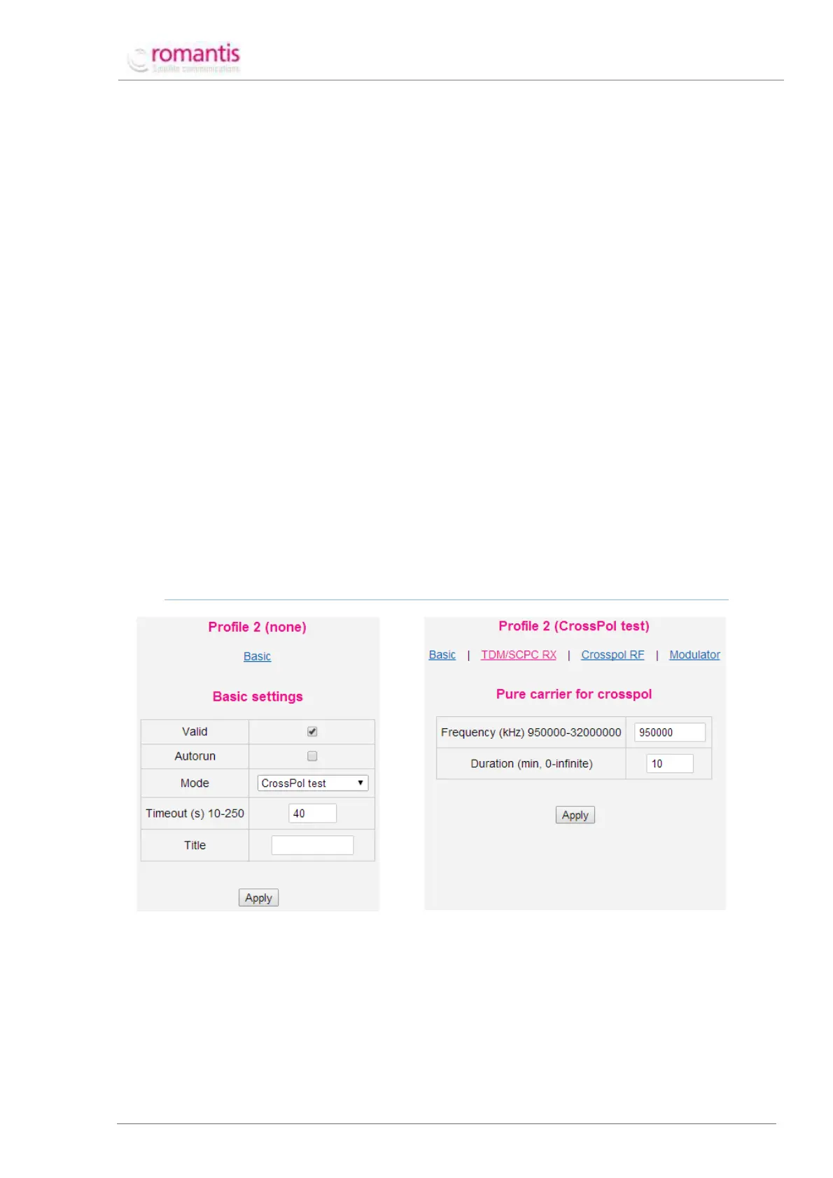
Create a new profile in CrossPol test mode. To create a profile, choose any unusable (having “None”
mode value) profile in the profile table (see Figure 33) and set CrossPol test value of the Mode setting;
AS THIS PROFILE WILL NOT BE USED CONSTANTLY AUTORUN FLAG IS NOT REQUIRED.
Figure 33 Create a CrossPol profile
Figure 34 Configure CrossPol profile
Specify the frequency of unmodulated carrier in CrossPol RF section of the profile which should be
provided by satellite operator;
Specify working duration of this profile. This value depends on duration of the measurement procedure.
Apply the settings.
2. Run CrossPol test profile manually;