UHP SCPC MODEM
USER MANUAL, v3.2
© ROMANTIS 2015 9 www.uhp.net
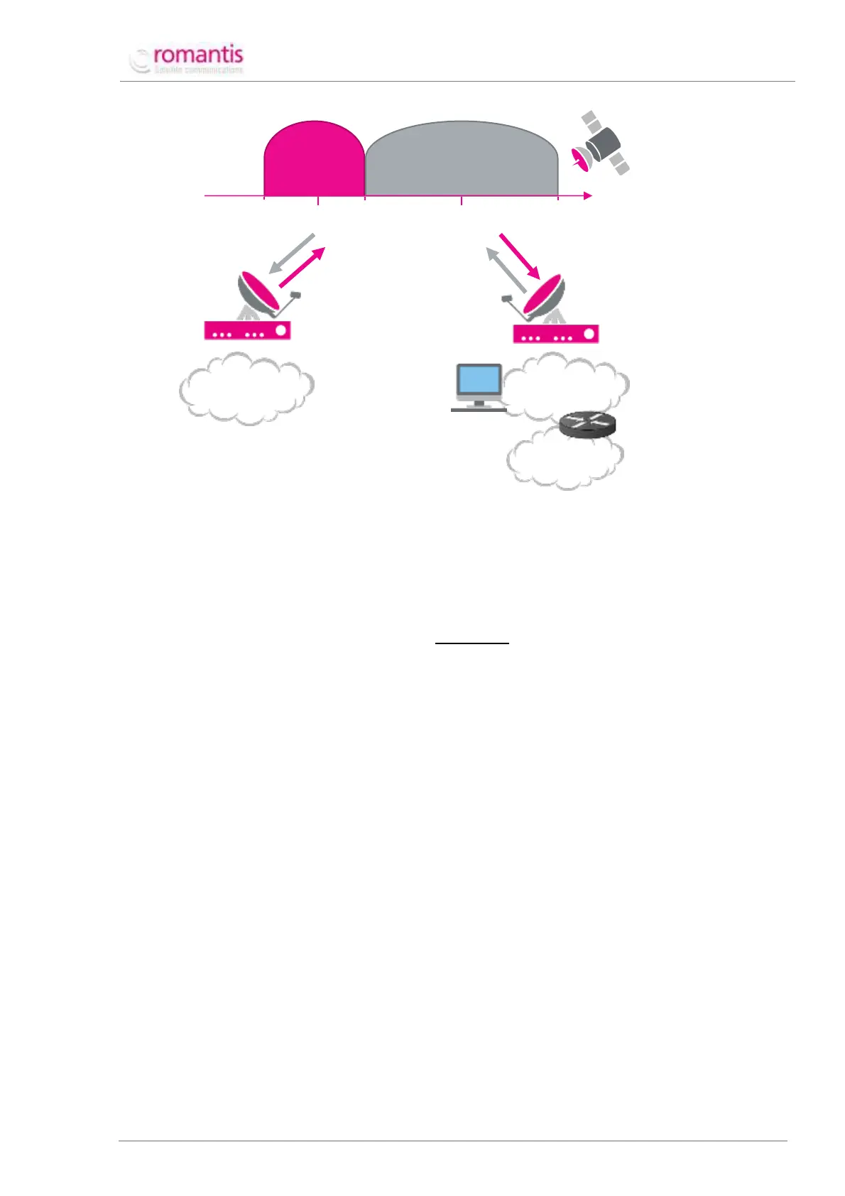
Figure 2 Example SCPC channel structure
A SCPC carrier of 2 MHz bandwidth (symbol rate 1667 KSps with roll-off=1.2) is used to transmit data from the
Station-1 to the Station-2, while another SCPC carrier of 1 MHz bandwidth (symbol rate 834 KSps with roll-off =
1.2) is used to transmit data from the Station-2 to Stations-1.
Bit rate and symbol rate are converted using the following formula:
SR =
BR
MOD ∗ FEC
where,
SR – symbol rate;
BR – bit rate;
MOD – modulation type (1 – BPSK, 2 – QPSK, 3 – 8PSK, 4 – 16APSK);
FEC – forward error correction rate.
The description below shows the procedure to establish SCPC connection between the Station-1 and Station-2:
Radio frequency channel configuration;
Transmission Level Control (TLC) configuration;
Adaptive Coding and Modulation (ACM) configuration;
Routing configuration;
Equipment redundancy mode configuration;
Pointing the antenna to the satellite;
Troubleshooting during UHP-routers operation;
SW and router settings storage/updating.
1.3 WEB-Interface
UHP-router WEB-interface (see Figure 3) is split into three areas:
1. Menu of commands;
2. Status bar;