UHP SCPC MODEM
USER MANUAL, v3.2
© ROMANTIS 2015 19 www.uhp.net
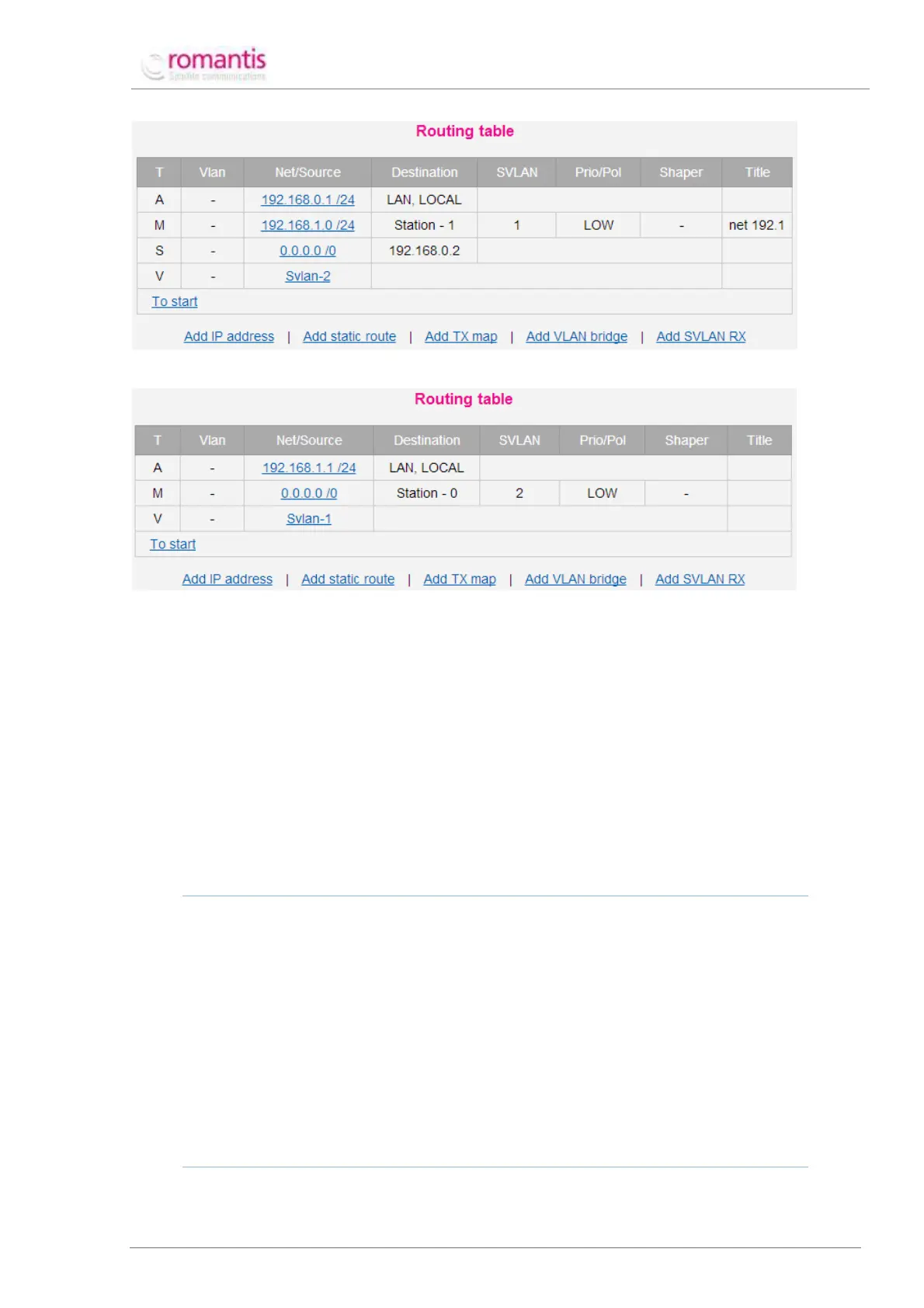
Figure 20 Routing table of Station-1
Figure 21 Routing table of Station-2
Entries in the routing table may have the following meaning:
M –SVLAN outgoing route (IP map);
V – Used for SVLAN receipt.
2.5 Redundancy
Station hot standby redundancy function is provided by a combination of two UHP routers with similar
configuration and similar modes of operation. Each router has to be connected to transmit and receive
paths according to the diagram below (see Figure 22).
WARNING! IF 10 MHZ REFERENCE SIGNAL IS REQUIRED FOR LNB (PLL LNB) BOTH TDMA RX INTERFACES SHOULD BE
ALSO CONNECTED TO THE RECEIVE PATH AS THERE IS NO 10MHZ REFERENCE SIGNAL ON SCPC RX INTERFACE.
The redundancy mode supports automatic switching the power and 10 MHz signals between routers. This
functionality requires that used IF splitters and combiners:
Have at least two ports;
Pass DC;
Pass 10 MHz reference signal.
This does not apply to RF equipment with other DC and 10 MHz reference signal sources.
POWER AND 10 MHZ REFERENCE SIGNALS SWITCH IS NOT SHOWN IN THE WEB INTERFACE OR IN RESPONSE TO
#SHOW INTERFACE MODULATOR TELNET COMMAND. FOR INSTANCE, IF THE ROUTER WAS INITIALLY CONFIGURED TO
POWER THE RF EQUIPMENT BUT LATER SWITCHED TO BACKUP MODE (BACKUP) AND STOPPED TO PROVIDE THE
POWER SUCH CHANGE WILL NOT BE SHOWN IN ITS STATISTICS.