Programable DC Electronic Load User Manual
53
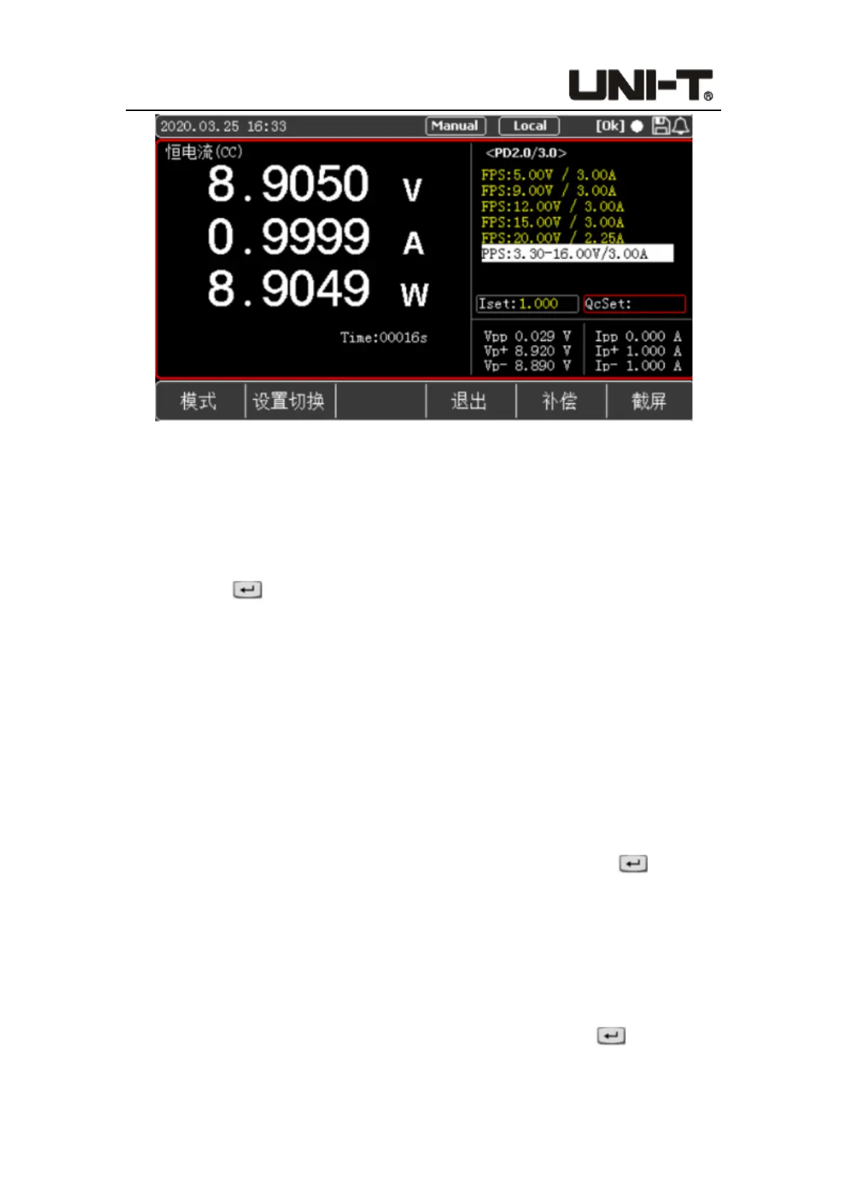
Figure 5-4-2 <PD2.0/3.0> Setting and Display Interface
PD2.0/3.0 test interface setting steps:
1. After entering the setting interface, press the soft key [Setting Switch] to switch the
selected box to carry out load setting or fast charge setting.
2. If users select the left box, they can input the load value with the keyboard, press the
Enter key to confirm the input value, and then press the ON button on the
panel. The system will load according to the initial voltage on the screen and the input
load value. It is also possible not to load immediately, and to load after performing
step 3.
3. Select the box on the right through [Setting Switch] to set the parameters of the fast
charge test. After entering the setting interface, the electronic load will automatically
have a handshake with the tested power supply and display the output voltage type
supported by the power supply on the screen. At this time, users can use the knob
and up/down keys to select the voltage to be triggered.
For fixed voltage point FPS and other types, as shown in Figure 5-4-1, after selecting
an FPS item with the knob and up/down keys, press the Enter key to trigger
the voltage, and the voltage input in the QcSet column is invalid. Then press the ON
button on the panel to load. After the load is successful, the ON button indicator will
turn green, the correct voltage and load value will be displayed on the screen, and the
OK symbol will be displayed on the upper right of the screen.
For types such as the programmable voltage item PPS, users can enter the required
voltage value through the QcSet column and press the Enter key to confirm. If
the input data is within the range, the Vset value will change accordingly. Then press
 Loading...