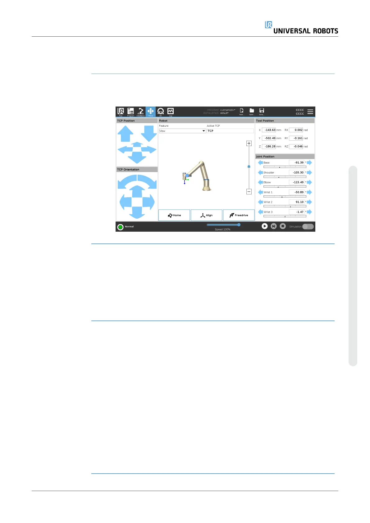
21.Move Tab
Description On this screen, you can move (jog) the robot arm directly, either by translating/rotating
the robot tool, or by moving robot joints individually.
Move Tool Hold down any of the Move Tool arrows to move the robot arm in a particular direction.
•
The Translate arrows (upper) move the robot tool-tip in the direction indicated.
•
The Rotate arrows (lower) change the orientation of the robot tool in the
indicated direction. The rotation point is the Tool Center Point (TCP), i.e.the point
at the end of the robot arm that gives a characteristic point on the robot’s tool.
The TCP is shown as a small blue ball.
Robot If the current position of the robot TCP comes close to a safety or trigger plane, or the
orientation of robot tool is near the tool orientation boundary limit (see Safety
PlanesModeson page154), a 3D representation of the proximate boundary limit is
shown. When the robot is running a program, the visualization of boundary limits is
disabled.
Safety planes are visualized in yellow and black with a small arrow representing the
plane normal, which indicates the side of the plane on which the robot TCP is allowed to
be positioned. Trigger planes are displayed in blue and green and a small arrow
pointing to the side of the plane, where the Normal mode limits (see 17.5 Software
Safety Modes on page143) are active. The tool orientation boundary limit is visualized
with a spherical cone together with a vector indicating the current orientation of the
robot tool. The inside of the cone represents the allowed area for the tool orientation
(vector).
When the robot TCP is no longer in proximity of the limit, the 3D representation
disappears. If the TCP is in violation or very close to violating a boundary limit, the
visualization of the limit turns red.
User Manual 317 UR10e
21.Move Tab
Copyright © 2009–2024 by UniversalRobotsA/S. All rights reserved.
 Loading...


