4.2. Controller I/O
Description You can use the I/O inside the Control Box for a wide range of equipment including
pneumatic relays, PLCs and emergency stop buttons.
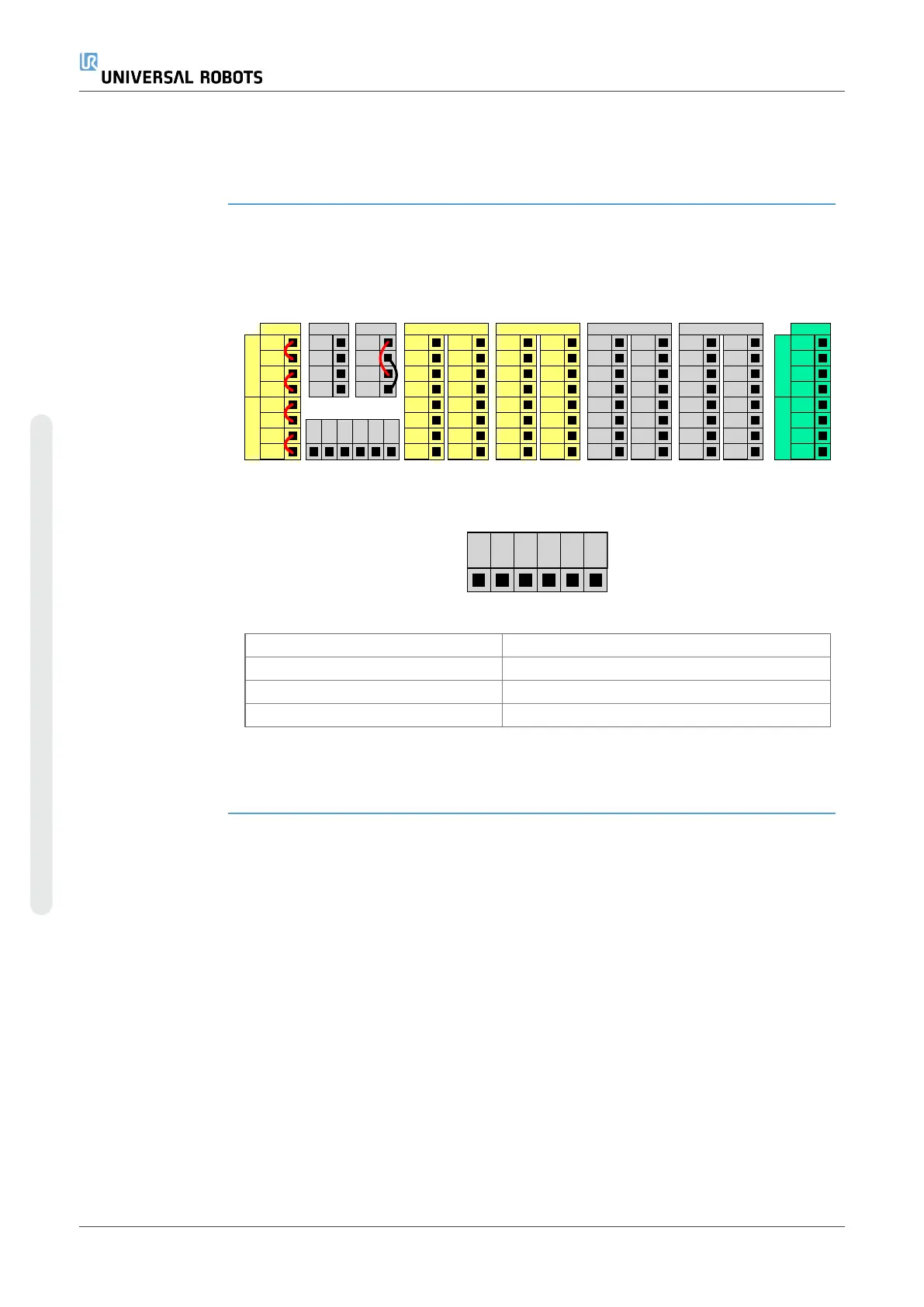
The illustration below shows the layout of electrical interface groups inside the Control
Box.
24V
EI1
24V
SI0
24V
SI1
24V
EI0
Safet y
ON
OF F
12V
Remote
24V
0V
P W R
GND
P ow er
24V
CI1
24V
CI2
24V
CI3
24V
CI0
Con figur ab le Inpu ts
24V
CI5
24V
CI6
24V
CI7
24V
CI4
0V
CO1
0V
CO2
0V
CO3
0V
CO0
Con figur ab le Outp ut s
0V
CO5
0V
CO6
0V
CO7
0V
CO4
24V
DI1
24V
DI2
24V
DI3
24V
DI0
Digital Inpu ts
24V
DI5
24V
DI6
24V
DI7
24V
DI4
0V
DO1
0V
DO2
0V
DO3
0V
DO0
Digital Outpu ts
0V
DO5
0V
DO6
0V
DO7
0V
DO4
AG
AI1
AG
AO0
AG
AO1
AG
AI0
Analog
Analog Outp uts
Analog Inp uts
Safeg uar d St op
Emerg en cy S top
GND
0V
24V
DI8
DI9
DI10
DI11
You can use the horizontal Digital Inputs block (DI8-DI11), illustrated below, for
quadrature encoding Conveyor Tracking (see Common specifications for all digital
I/Oon the facing page) for these types of input.
The meaning of the color schemes listed below must be observed and maintained.
Yellow with red text Dedicated safety signals
Yellow with black text Configurable for safety
Gray with black text General purpose digital I/O
Green with black text General purpose analog I/O
In the GUI, you can set up configurable I/O as either safety-related I/O or general
purpose I/O (see partPart II PolyScope Manual).
UR10e 48 User Manual
4. Electrical Interface
Copyright © 2009–2024 by UniversalRobotsA/S. All rights reserved.
 Loading...


