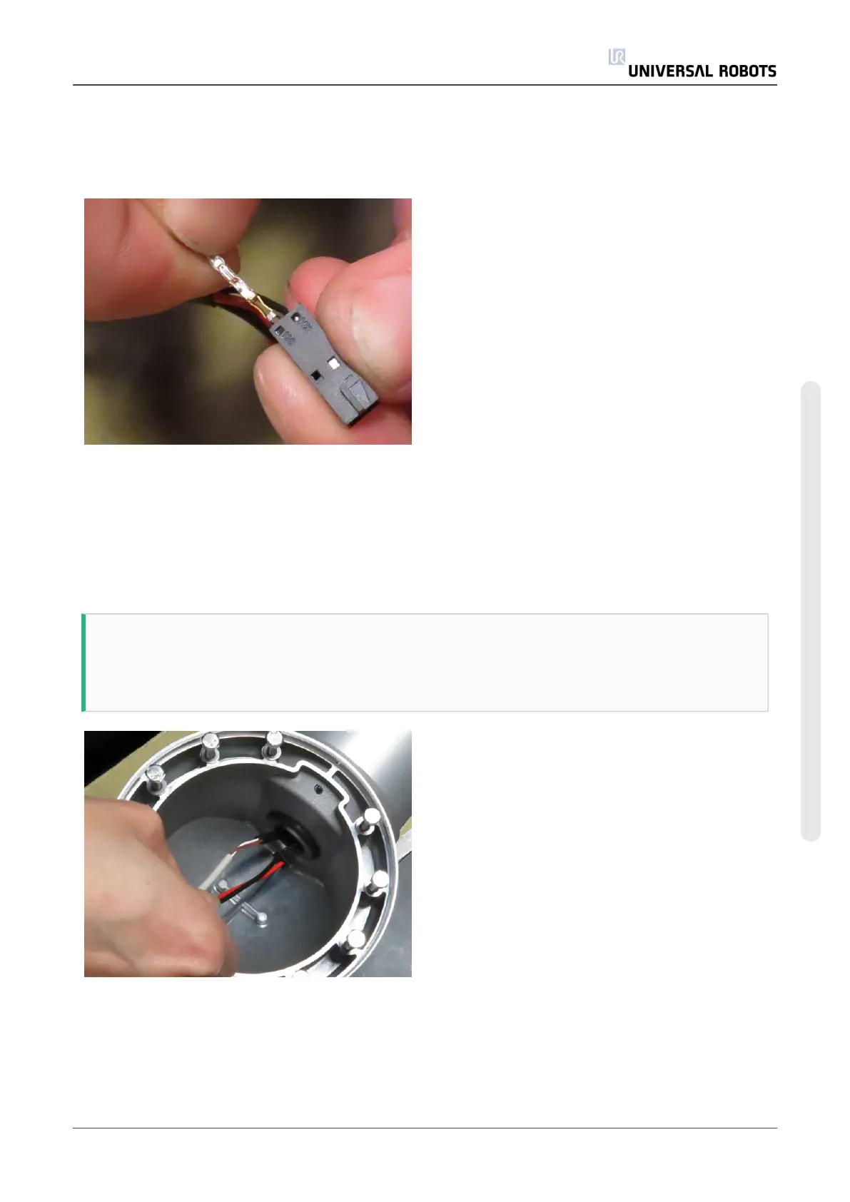
• Take the communication connector:
• When inserting the connector pins, make
sure the barbs, shown with green arrows,
are located as shown on the photo. If
not, they will not hook inside the
connector and will fall out.
• Inset the black connector pin into the
plug hole marked “MX”. Remember to
orientate the barbs as described above.
A “click” will be heard when inserted
correctly.
• Inset the white pin in the other plug hole.
• When done, check that the connector
pins are firmly hooked inside the plug by
pulling gently in the wires.
• If not, check that the orientation of the
barbs is correct. If inserted correctly,
use a tool to press on the pins to ensure
they are pushed all the way in.
Lower arm – part number: 103508
NOTE
The lower arm wire bundle kit contains wire bundle for multiple robot types.
Please be sure use the correct length.
• Slide the end with the two black
connectors through the hole from the
elbow end – see photo example.
Service Manual 51 UR5
5.Service and Replacement of parts
Copyright © 2009–2021 by UniversalRobotsA/S. All rights reserved.