• Unscrew the motherboard by loosening the 4 x 2.5mm hex screws and the 4 x 5,5 hex
standoffs that hold the RS232 and DVI connectors
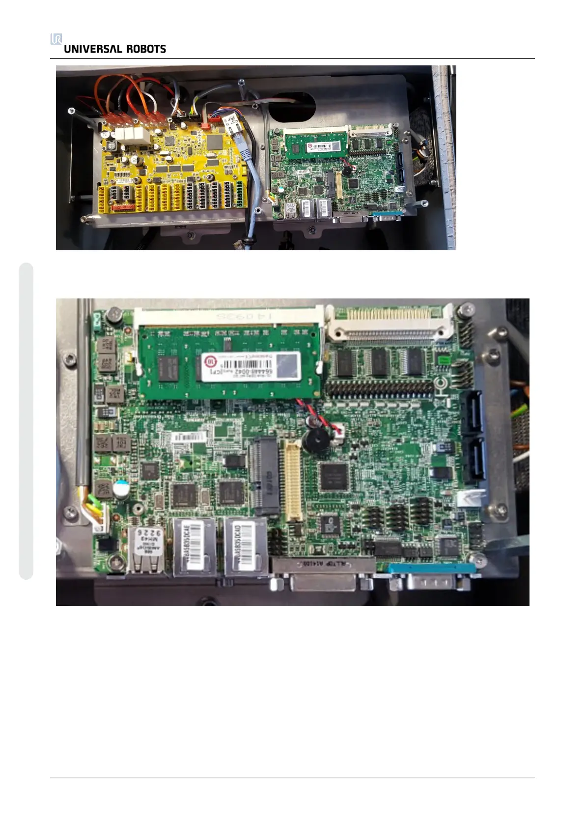
• Mount the smaller standoffs where the motherboard screws were before. Place the black
cable from the Teach Pendant and the Ethernet cable on the left side of the Standoff as
shown on the photo. Note: If your Ethernet cable has a black plug (Figure 1) at one end,
then this end must be connected to the Safety Control Board.
UR5 60 Service Manual
5.Service and Replacement of parts
Copyright © 2009–2021 by UniversalRobotsA/S. All rights reserved.