2GM
2-3-25
Connector Pin No. Signal I/O Description
K1 K5
K2
K3
K4
K6
K7
K8
U3
U1
U2
U4
U7
U6
X1
X2
YC5
YC3
YC6
YC7
K9 K13
K17
K10
YC2
YC1
K11
K12
K14 K18
K15
K16
K19
K20
K21 K22
K23
K24
K26
K28
K29
K30
K27
K25
K31
K32
K33
K34
K37
K38
K40
K41
K43
K44
K42
K35
K36
K39 K45
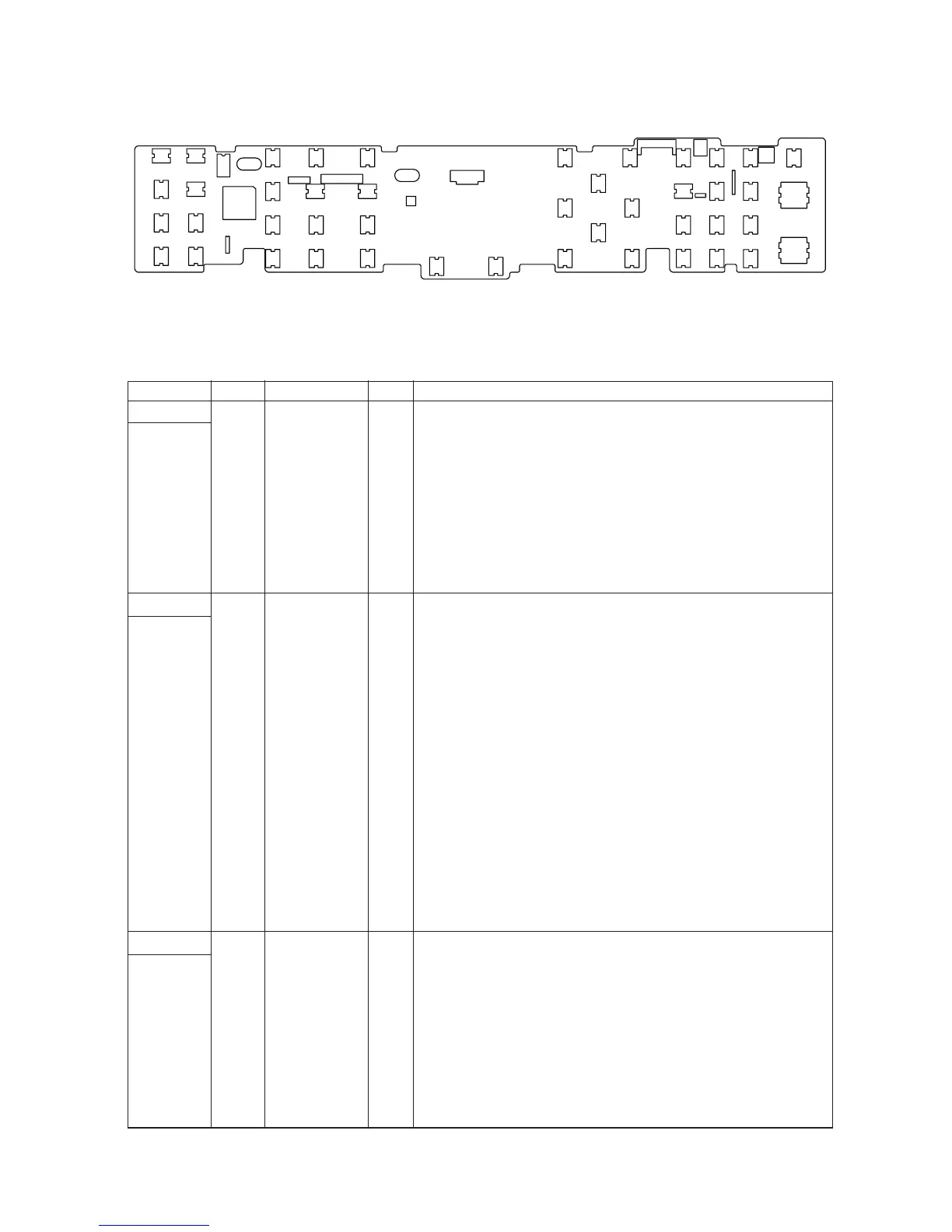
Figure 2-3-19 Operator PWB silk-screen diagram
YC3
Connected
to the main
PWB
YC5
Connected
to the LCD
YC6
Connected
to the
speaker
1 SGND - Ground
2 AUDIO I AUDIO signal
3 +5 V I 5 V DC power supply
4 FPRST I FPRST signal
5 PANTXD I PANTXD signal
6 PANRXD O PANRXD signal
7 PANRTS I PANRTS signal
8 PANCTS O PANCTS signal
9 +3.3 V I 3.3 V DC power supply
10 CHECK I CHECK signal
11 TEMP O Temperature detection data
1 SGND - Ground
2 V5 O V5 signal
3 V4 O V4 signal
4 V3 O V3 signal
5 V2 O V2 signal
6 V1 O V1 signal
7 CAP2+ O CAP2+ signal
8 CAP2- O CAP2- signal
9 CAP1- O CAP1- signal
10 CAP1+ O CAP1+ signal
11 CAP3- O CAP3- signal
12 Vout - Ground
13 Vss - Ground
14 Vdd O 3.3 V DC power supply
15 SI O SI signal
16 SCL O SCL signal
17 A0 O A0 signal
18 /RES O /RES signal
19 /CS1 O /CS1 signal
20 SGND - Ground
1 OUT- O OUT- signal
2 OUT+ O OUT+ signal