Safety vacon • 8
Service support: find your nearest Vacon service center at www.vacon.com
1
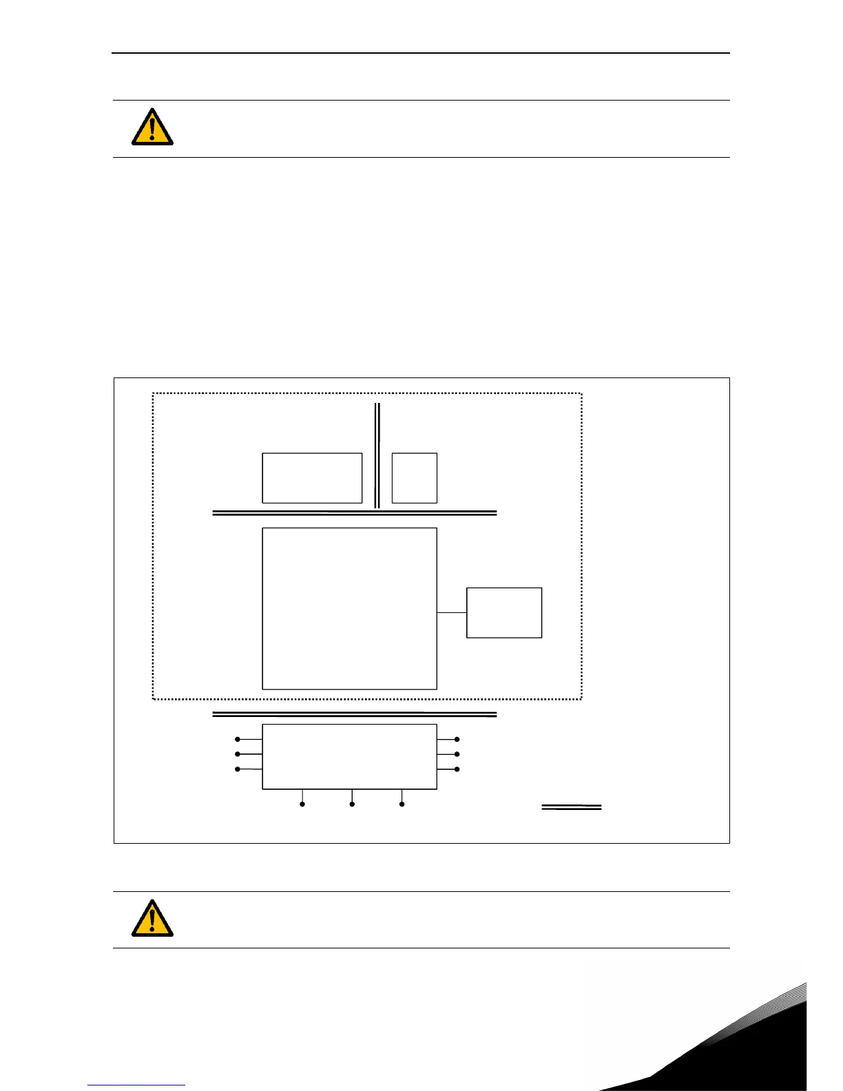
1.6 Insulation system
A distinction has to be made for the following three groups of terminals, according the insulation
system of VACON
®
100 X:
• Mains and motor connections (L1, L2, L3, U, V, W)
• Relays (R01, R02)
(*)
• Thermistor-input
• Control terminals (I/Os, RS485, Ethernet, STO)
The Control terminals (I/Os, RS485, Ethernet, STO) are isolated from the Mains (the insulation is re-
inforced, according to IEC 61800-5-1) and the GND terminals are referred to PE.
This is important when you need to connect other circuits to the drive and test the complete assem-
bly. Should you have any doubt or question, please contact your local VACON
®
distributor.
Figure 4. Insulation system.
Please, consider carefully the insulation system depicted in Figure 4 before connect-
ing any circuit to the unit.
(*)
The relays may be used also with DVC A circuits. This is possible only if both relays
are used with DVC A circuit: to mix Mains and DVC A is not allowed.

 Loading...


