Control unit vacon • 44
Service support: find your nearest Vacon service center at www.vacon.com
5
5. CONTROL UNIT
Remove the powerhead of the drive to reveal the terminal box with the control terminals.
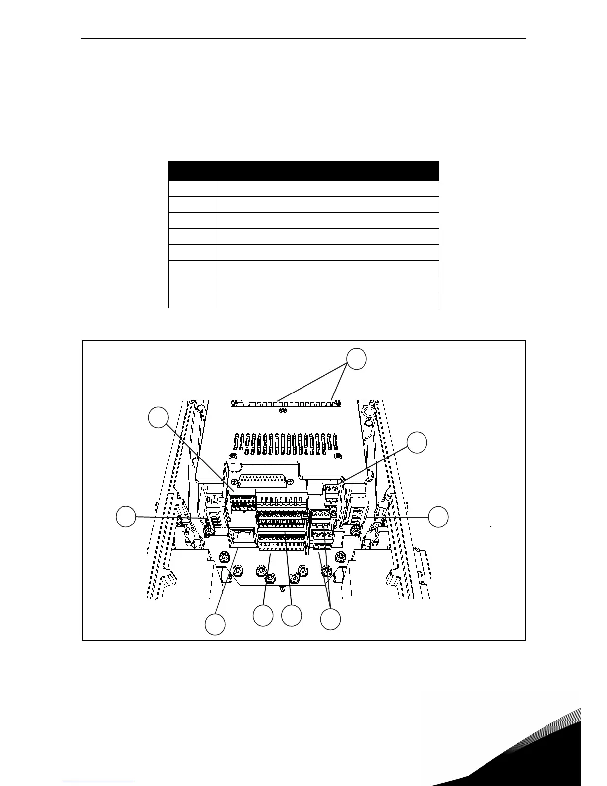
The control unit of the AC drive consists of the control board and additional boards (option boards)
connected to the slot connectors of the control board. The locations of boards, terminals and
switches are presented in Figure 30 below.
Figure 30. Locations of components in control unit.
When delivered from the factory, the control unit of the AC drive contains the standard controlling
interface - the control and relay terminals of the control unit - unless otherwise specifically or-
dered. On the next pages you will find the arrangement of the control I/O and the relay terminals,
the general wiring diagram and the control signal descriptions.
Number Meaning
1 Control terminals 1-11 (see chapter 5.1.2)
2 Control terminals 12-30, A-B (see chapter 5.1.2)
3 Relay terminals (see chapter 5.1.2)
4 Thermistor input (see chapter 5.1.2)
5STO terminals
6Dip switches
7 Ethernet terminal (see chapter chapter 5.2.1)
8 Option boards
Table 17. Locations of components in control unit.

 Loading...


