3
vacon • 30 Descriptions of VACON® option boards
Local contacts: http://drives.danfoss.com/danfoss-drives/local-contacts/
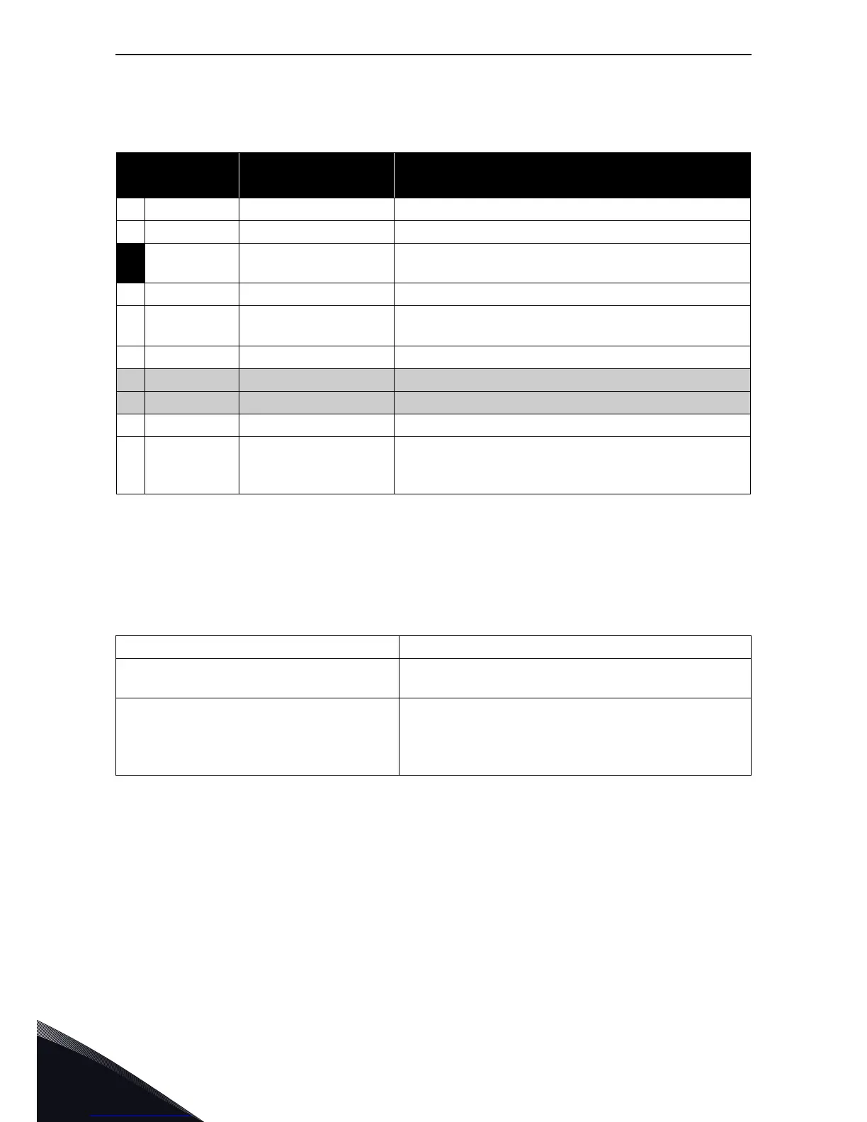
I/O terminals on OPTA5 (coded terminal painted black)
NOTE: Encoder inputs are wide range inputs that can be used with encoders using +15V or +24V.
Technical data:
NOTE: A high pulse frequency combined with a great cable capacitance places a considerable load
on the encoder. Apply therefore as low a voltage as possible for the encoder supply, rather lower
than 24V. The manufacturer also recommends to place jumper X4 to position +15V, if allowed in the
voltage range specification of the encoder.
Table 11. OPTA5 I/O terminals
Terminal
Parameter reference
Keypad/NCDrive
Technical information
1 DIC1A+ Pulse input A (differential); Voltage range 10…24V
2 DIC1A–
3 DIC2B+
Pulse input B; phase shift of 90 degrees compared to
Pulse input A (differential); Voltage range 10…24V
4 DIC2B–
5
DIC3Z+
Pulse input Z; one pulse per revolution (differential);
Voltage range 10…24V
6 DIC3Z–
7 ENC1Q Reserved for future use
8 DIC4 Reserved for future use
9 GND Ground for control and inputs ENC1Q and DIC4
10
+15V/+24V
Control voltage (auxiliary voltage) output to encoder;
Output voltage selectable with jumper X4. See chapter
1.4.4.
Encoder control voltage, +15V/+24V Control voltage selectable with jumper X4.
Encoder input connections,
inputs A+, A–, B+, B–, Z+, Z–
Max. input frequency ≤150kHz
Inputs A, B and Z are differential
Qualifier input ENC1Q
Fast digital input DIC4
Max. input frequency ≤10kHz
Min. pulse length 50μs
Digital input 24V; R
i
>5kΩ
Digital input is single-ended; connected to GND
 Loading...


