3
vacon • 46 Descriptions of VACON® option boards
Local contacts: http://drives.danfoss.com/danfoss-drives/local-contacts/
I/O terminals on OPTAE (coded terminal painted black)
NOTE: Encoder inputs are wide range inputs that can be used with encoders using +15V or +24V.
Technical data:
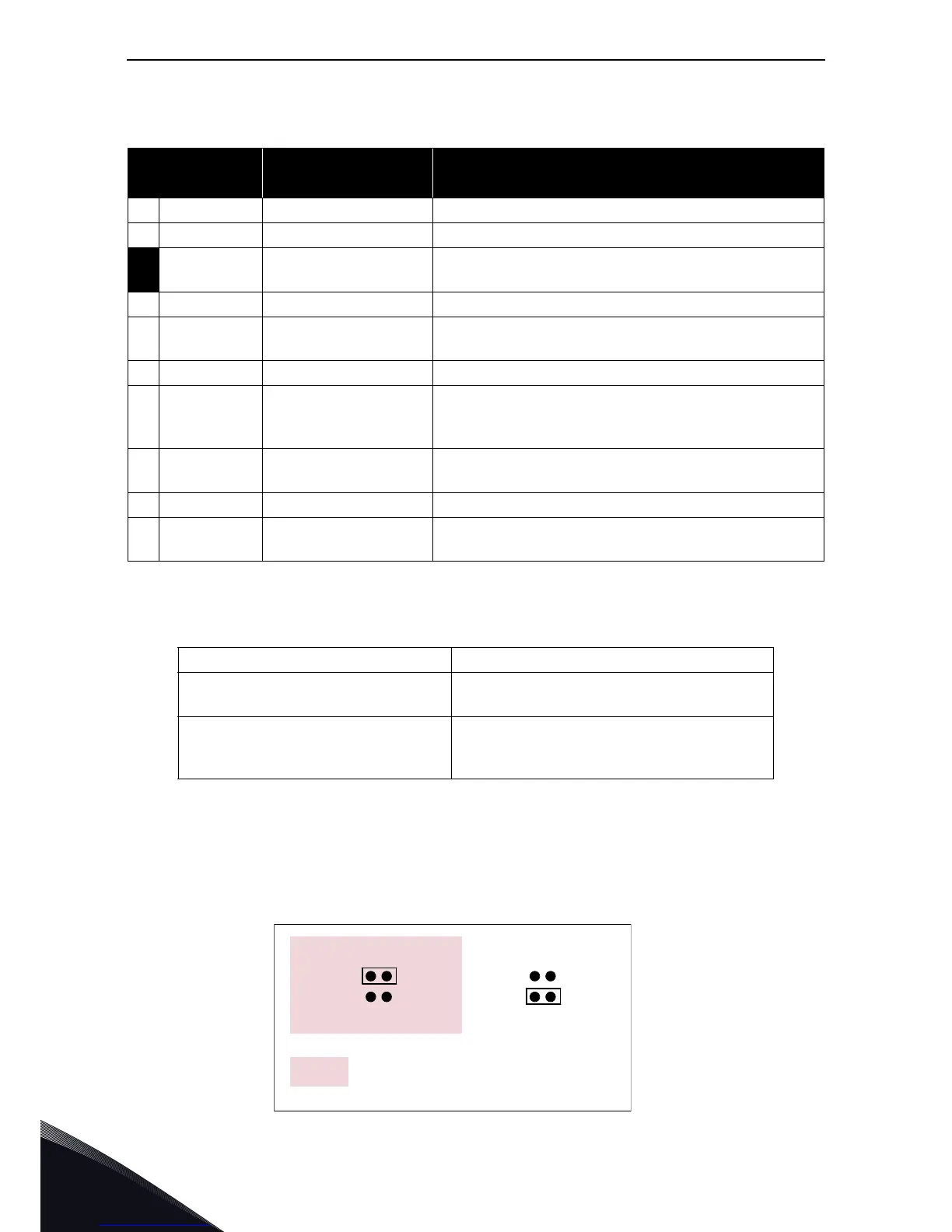
Jumper selections
On the OPTAE board, there is one jumper block used to program the control voltage (auxiliary
voltage). The factory default and other available jumper selections are presented below.
Table 18. OPTAE I/O terminals
Terminal
Parameter reference
Keypad/NCDrive
Technical information
1 DIC1A+ Pulse input A (differential); Voltage range 10…24V
2 DIC1A–
3 DIC2B+
Pulse input B; phase shift of 90 degrees compared to
Pulse input A (differential); Voltage range 10…24V
4 DIC2B–
5
DIC3Z+
Pulse input Z; one pulse per revolution (differential);
Voltage range 10…24V
6 DIC3Z–
7
DO1
Encoder divider output. Encoder input signals are
divided by divider paramater (see parameter list on
page 48)
8
DO2
Encoder direction output. The signal value ‘1’ means
that the motor direction is backward and ‘0’ is forward.
9 GND Ground for control
10
+15V/+24V
Control voltage (auxiliary voltage) output to encoder;
Output voltage selectable with jumper X4.
Encoder control voltage, +15V/+24V Control voltage selectable with jumper X4.
Encoder input connections,
inputs A+, A–, B+, B–, Z+, Z–
Max. input frequency ≤150kHz
Inputs A, B and Z are differential
Encoder divider output DO1,
Encoder direction output DO2
Max.load voltage 60Vdc
Max. load current 50mA
Max. output frequency ≤300kHz
 Loading...


