3
vacon • 38 Installation
Tel. +358 (0) 201 2121 • Fax +358 (0)201 212 205
3.6.3 Control connections
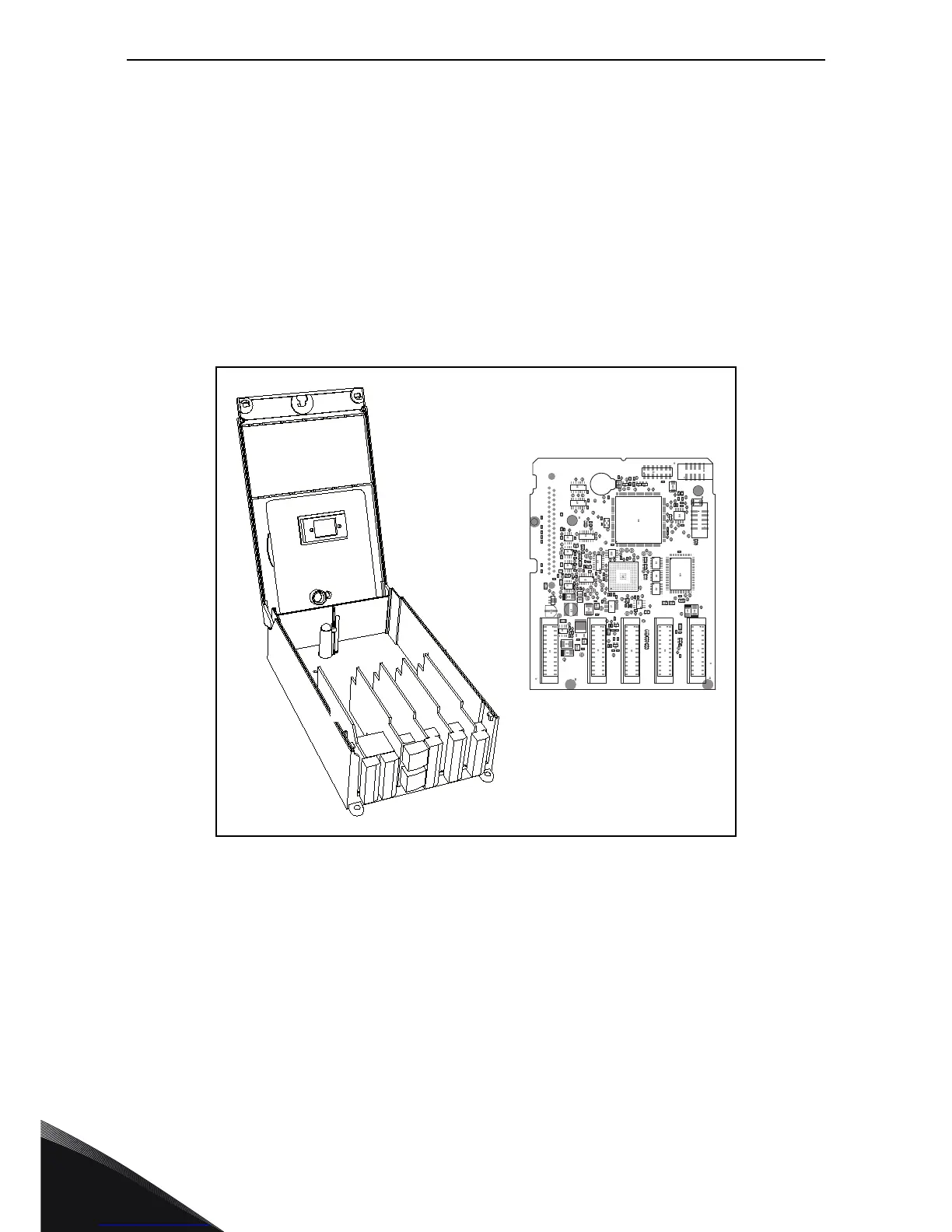
The control unit of the AC drive consists roughly of the control board and additional boards
connected to the five slot connectors (A to E) of the control board. The control board is connected to
the power unit through a D-connector or fibre optic cables.
Usually, when the frequency converter is delivered from the factory, the control unit includes at least
the standard compilation of two basic boards (I/O board and relay board) which are normally
installed in slots A and B.
The control board can be powered externally (+24V, ±10%) by connecting the external power source
to either of the bidirectional terminals. This voltage is sufficient for parameter setting and for
keeping the fieldbus active.
For more detailed cabling instructions, see the corresponding user manual (see Table 2 on page 5).
Figure 24. Control unit, control board (right) and option boards (A-E)
AB
B
C
C
D
D
E
E
A
13872_00
 Loading...


