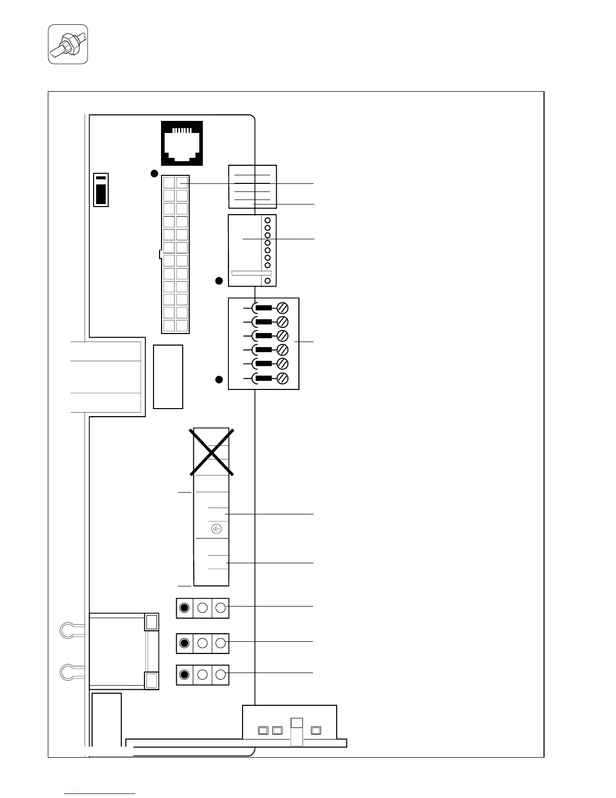
Socket X2 for internal unit components
Socket X4 for minority reversing valve
Socket X7 for accessory box connection
Socket X8 for VRC-VC connection
Room thermostat, 230 V: connections 3, 4 and 5
Mains power supply: connections L, N and earth
Socket X12: pump connection
Socket X14: gas valve connection
Socket X13: fan unit connection
Do not use!
Electronic board layout
Fig. I.13: Connection wiring
 Loading...