EasyManuals Logo

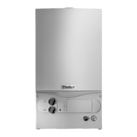
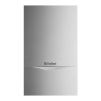
Vaillant TURBOmax Plus SERIES User Manual

Vaillant TURBOmax Plus SERIES
92 pages
To Next Page IconTo Next Page
To Previous Page IconTo Previous Page
Page #85 background imageLoading...
Page #85 background image
85
DIAGRAMS
POWER SUPPLY
F2A
L
2
N
1
MAIN SWITCH
MAIN
TRANSFORMER
230V
20V
AIR
PRESSURE
SWITCH
FAN
PUMP
NTC FLOW
TEMPERATURE
SENSOR
FLAME
SENSOR
GAS
VALVE
DHW
Aqua
Sensor
F1,25A
NTC RETURN
TEMPERATURE
SENSOR
Burner lock out
indicator (red)
Hot water/warmstart
demand indicator
Ignition indicator
MAIN SWITCHBOARD
IGNITION
ELECTRODES
Legend
b blue
br brown
y/g yellow/green
r red
p pink
or orange
t transparent
bl black
gr grey
w white
gr
b
br
y/g
bbr
y/g
br
t
w
p
t
br
br
r
b
br
y/g
gr
p
p
r
CONTROL BOX
DIVERTER
VALVE
bl
bl
bl
bl
NTC
WARMSTART
TEMPERATURE
SENSOR
or
plug in
connector
display
plus / minus buttons
reset button
info button
Fig. D.1: Functional Flow diagram VUW
Euro B/S 175/0
Functional Flow diagram: TURBOmax Plus 824/2 E, 828/2 E
TURBOmax Plus

Table of Contents

Questions and Answers:

Question and Answer IconNeed help?

Do you have a question about the Vaillant TURBOmax Plus SERIES and is the answer not in the manual?

Vaillant TURBOmax Plus SERIES Specifications

General IconGeneral
CategoryBoiler
ModulationYes
ModelTURBOmax Plus SERIES
Fuel typeNatural gas
MountingWall-mounted
Heating CircuitSingle
Output24kW, 28kW
Warranty2 years (extendable)

Related product manuals