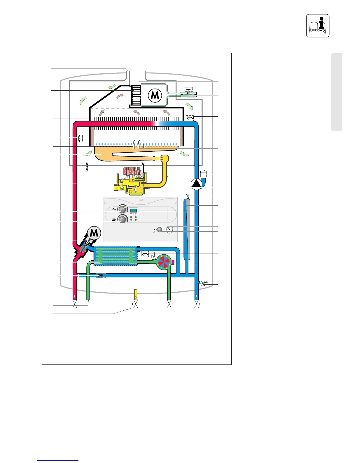
EasyManuals Logo

Vaillant TURBOmax Plus SERIES User Manual

Vaillant TURBOmax Plus SERIES
92 pages
To Next Page IconTo Next Page
To Previous Page IconTo Previous Page
Page #9 background imageLoading...
Page #9 background image
BOILER SPECIFICATION
9
Functional Diagram
(TURBOmax Plus)
u
C
C
i
1
2
3
4
5
6
7
8
9
10
11
12
13
14
15
17
16
18
19
20
21
22
23
24
25
26
27
28
29
30
31
1 Air duct
2 Fan
3 Main heat exchanger
4 Temperature sensor (NTC I)
5 Flame sensing electrodes
6 Modulating burner
7 Fully modulating automatic gas
value
8 Maximum hot water temperature
control
9 Maximum radiator temperature
control
10 Diverter valve
11 DHW heat exchanger
12 Automatic bypass valve
13 CH flow service valve
14 Hot water outlet
15 Gas service valve
16 Cold water service valve
17 CH return service valve
18 Pressure relief valve
19 Aqua sensor (DHW flow switch)
20 Temperature sensor (NTC III)
21 Main on/off control
22 Pressure gauge
23 Display
24 Expansion vessel
25 Expansion vessel charging valve
26 Circulating pump
27 Automatic air vent
28 Ignition electrode
29 Temperature sensor (NTC II)
30 Air pressure switch
31 Flue gas duct
Fig. B.3: Functional Diagram TURBOmax Plus
Euro B/S 196/0
TURBOmax Plus

Table of Contents

Questions and Answers:

Question and Answer IconNeed help?

Do you have a question about the Vaillant TURBOmax Plus SERIES and is the answer not in the manual?

Vaillant TURBOmax Plus SERIES Specifications

General IconGeneral
CategoryBoiler
ModulationYes
ModelTURBOmax Plus SERIES
Fuel typeNatural gas
MountingWall-mounted
Heating CircuitSingle
Output24kW, 28kW
Warranty2 years (extendable)

Related product manuals