33
BOILER INSTALLATION SEQUENCE
Controls
(TURBOmax Plus boiler)
External electrical controls
The boiler terminals 3, 4 and 5 are
for connecting external
electrical controls such as a time
switch and/or room thermostat.
Terminals 3 and 4 are linked together
when the boiler is supplied. If external
controls are used, this link must be
removed, and the controls connected
across terminals 3 and 4.
Terminal 5 is an additional neutral
connection for external neutrals such
as from the anticipator of a room
thermostat.
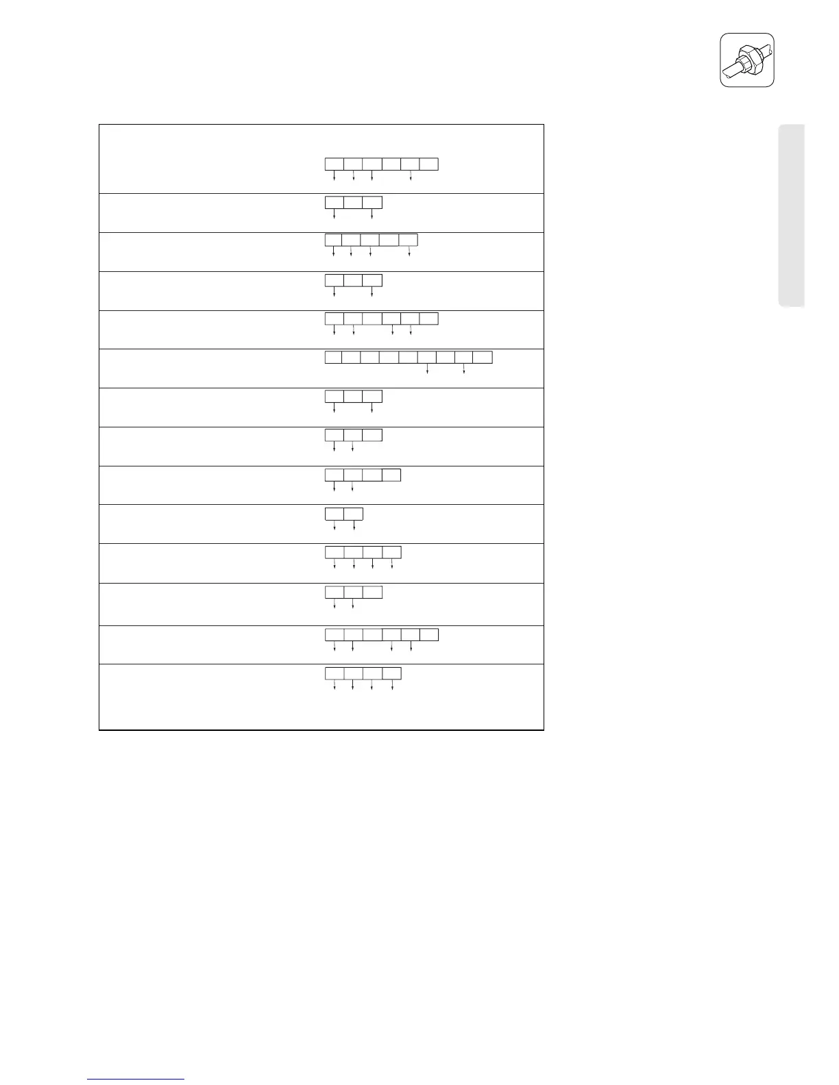
Connection of external controls
Connection details for programmable
room thermostats.
Fig. I.14 shows the connection details
where a programmable room
thermostat (time switch with built in
room thermostat) is used to control the
boiler.
Important: The arrowed numbers
indicate connection into the relevant
terminal in the boiler terminal strip.
Connection details for programmable thermostats
LN
234
LN3
4
1
ACL Drayton
Lyfestyle PT271, PT371
ACL Drayton
Digistat 2, 3, 4
ACL Drayton
Digistat RF - SCR Receiver
Danfoss Randall
TP4, TP5, TP5E
Danfoss Randall
TP5E RF with receiver RX1
Danfoss Randall
TP75
Grässlin Towerchron
RTC7
Honeywell
CM61, CM67, CM31, CM37
Horstmann
Centaurstat 1, 7
Landis & Staefa
REV 11, REV 15, REV 22
12
34
3
Sunvic
TLX 6501
Sunvic
TLX RFP, TLX RFD
Vaillant
VRT 9083QT, VRT 9084QW
N1
3
N3
2
L
L
4
32
43
1
LN
234
LN 3
4
1
BC
2341
A
3
56
4
12
34
3
AB
34
C
12
4
34
3
LL1
34
Smiths Timeguard
ProgramaSTAT PRT11, PRT17
LN
4
LN
3
34
12
34
3
LN
234
LN 3
4
1
F9
8
LN
7
34
 Loading...