User's Guide _______________________________________________________________________
10 ___________________________________________________________________ M210865EN-H
- Configurable alarm modes for analog outputs
- Digital output: RS-485
- Serial line connection also via USB serial interface cable
- Simultaneous use of analog and digital output possible
- Field check suitability with DM70 hand-held meter
- Optional sampling cells with different installation options available as
DMT152 installation accessories
- LED cable option that enables a visual indication of transmitter status:
LED lit when measurement is frozen (for example, purge active),
blinking for malfunction alarm
* When the dewpoint is below 0 °C, the transmitter outputs frostpoint
for T
d
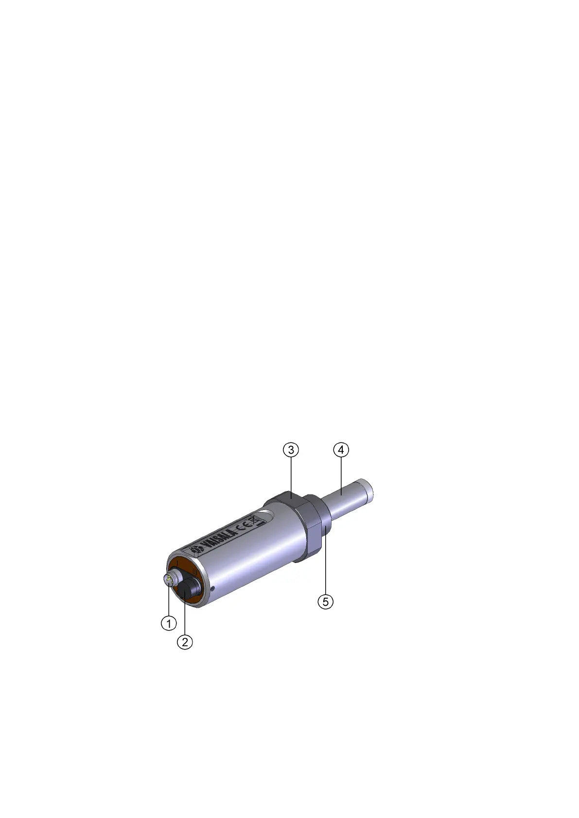
Transmitter Structure
When the transmitter is delivered, the filter is protected by a yellow
transport protection cap that keeps the sensor dry. The transport
protection cap should be left on the transmitter during storage. Remove
the transport protection cap before installing the transmitter.
The transmitter body does not have user serviceable parts inside, and is
not designed to be opened. Opening the transmitter will void the
warranty.
0710-151
Figure 1 Dewpoint Transmitter DMT152
4-pin M8 connector I: analog output channels and operating
power