User's Guide _______________________________________________________________________
4 ____________________________________________________________________ M210865EN-H
List of Figures
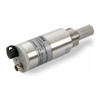
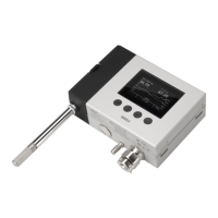
Figure 1 Dewpoint Transmitter DMT152 ................................................. 10
Figure 2 DMT152 Installed Directly to Pipeline....................................... 15
Figure 3 Removing the Transport Protection Cap .................................. 15
Figure 4 Installing the Transmitter .......................................................... 16
Figure 5 Connecting the Cable ............................................................... 16
Figure 6 Connectors I and II ................................................................... 18
Figure 7 Connector Pinout ...................................................................... 18
Figure 8 Output Noise Minimization Wiring Option ................................. 19
Figure 9 Cable with Snap-On Connector ................................................ 20
Figure 10 Cable with Threaded Connector ............................................... 21
Figure 11 LED Cable ................................................................................ 21
Figure 12 USB Serial Interface Cable ....................................................... 21
Figure 13 DMT242SC2 (left) and DMT242SC (right) ............................... 24
Figure 14 DSC74 Sampling Cell with Accessories ................................... 25
Figure 15 DSC74B .................................................................................... 26
Figure 16 Removing Leak Screw .............................................................. 27
Figure 17 Default Assembly of DSC74C .................................................. 28
Figure 18 Alternative Assembly of DSC74C (for Tight Spaces) ............... 29
Figure 19 NW40 Mounting Flange ............................................................ 30
Figure 20 NW40 Mounting Flange Dimensions ........................................ 30
Figure 21 PuTTY Terminal Application ..................................................... 33
Figure 22 Filter Structure .......................................................................... 55
Figure 23 Supply Voltage Too Low for mA Output Error .......................... 56
Figure 24 Accuracy Over Temperature Range ......................................... 62
Figure 25 DMT152 Dimensions ................................................................ 66
List of Tables
Table 1 Manual Revisions ....................................................................... 6
Table 2 Related Manuals ......................................................................... 6
Table 3 Quantities Measured by the DMT152 ......................................... 9
Table 4 Standard Wiring Pinouts and Wire Colors ................................ 18
Table 5 Output Noise Minimization Wiring Option
Pinouts and Wire Colors ........................................................... 20
Table 6 DMT152 Default Serial Interface Setting .................................. 32
Table 7 DMT152 Serial Commands ...................................................... 34
Table 8 FORM Command Quantities .................................................... 42
Table 9 FORM Command Modifiers ...................................................... 43
Table 10 Pressure Conversion Coefficients ............................................ 46
Table 11 Error Codes .............................................................................. 60
 Loading...
