3.2 Indigo200 transmitter base
INDIGO 201 ANALOG
OUTPUT TRANSMITTER
Serial No. SX12345678
1 2 3
4
5
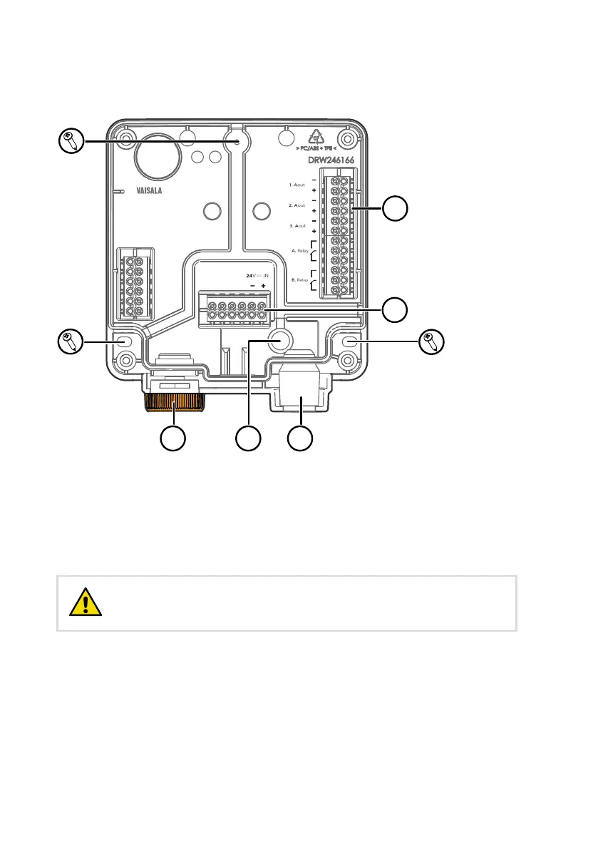
Figure 6 Indigo 201 transmitter base main parts and mounting screw positions
1
Probe and probe cable connector inside the locking wheel
2 Wiring from the back: cut open the seal
3 Rubber cable lead-through with strain relief
4 Screw terminals for analog outputs 1-3 and relays A and B
5 Screw terminals for 24 V power supply input
Do not energize the power supply before the wiring has been
connected.
CAUTION!
Indigo201 User Guide M212842EN-B
16