• If you replace a probe with a new one that has the same measurement parameters as the
removed probe, the transmitter will continue to show those measurements once it detects
the new probe. Outputs will give an error notification, which will disappear when the new
probe is detected.
• If you replace a probe with a new one that has dierent measurement parameters as the
removed probe, you need to reconfigure the measurement parameters and outputs for
the new probe.
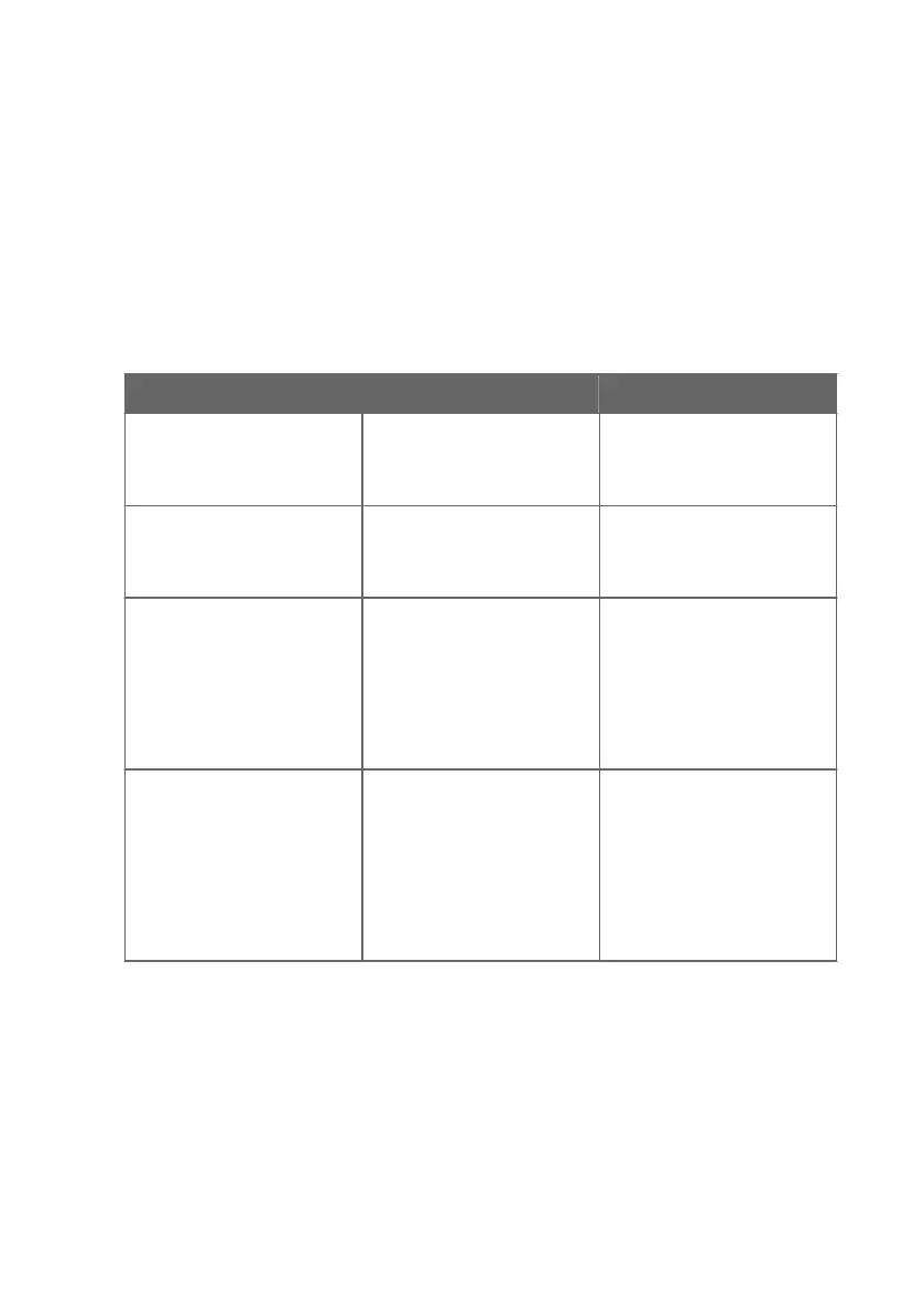
8.3 Troubleshooting
Problem Possible Cause Remedy
USB connection to Insight PC
software cannot be established
USB connection has been
disabled with the DIP switch on
the transmitter component
board.
See the instructions in
Disabling and enabling USB
functionality with DIP switch
(page 27).
Functionalities are not available
in Insight PC software.
Insight PC software is in Basic
Mode. Certain functionalities
are only available in Advanced
Mode.
Change the user mode from
Basic Mode to Advanced Mode
in the Insight PC software main
view Settings menu.
Measurement performance
aected after calibration.
Probe has not been switched
from calibration mode to
normal operating mode in the
Insight PC software.
Open the calibration menu in
the Insight PC software
(Configure Device > Calibrate).
Exit the calibration menu with
the Close selection, and ensure
that you confirm closing the
calibration mode when exiting
with the Yes selection.
Analog output appears
incorrect.
The analog output channel
Adjustment mode has not
been switched o after
adjustment.
Open the analog output
adjustment menu in the Insight
PC software and switch the
adjustment mode o. See
Analog output configuration
overview (page 28). Note that
each of the 3 analog outputs
has its own configuration
menu.
8.4 Display messages
The following table lists the display messages that Indigo 201 uses to inform you about the
transmitter's state.
In addition to the Indigo transmitter messages, the connected probes have probe-specific
messages that are also shown on the display. Messages from the connected probe start with
Probe:. For more information on the probe-specific messages, see the probe's documentation.
Chapter 8 – Maintenance and troubleshooting
47
 Loading...