2. To wire the input/output cable through the rubber lead-through on the bottom:
a. Push the input/output cable through the lead-through.
b. The lead-through provides strain relief and holds the cable in place. Tightening is not
required.
The recommended cable diameter for wiring through the rubber lead-
through is 7 ... 8 mm. If you use a dierent cable size, test that the strain relief
works as intended.
3.4 Inputs and outputs
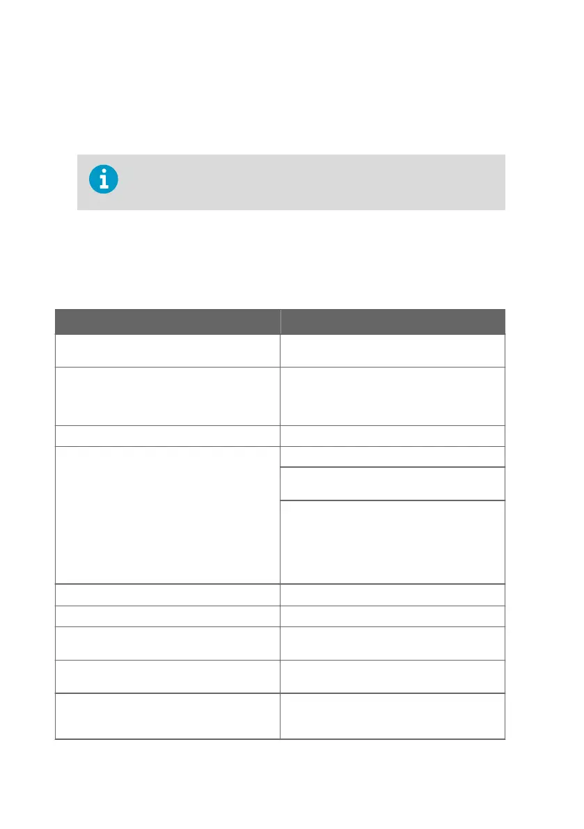
Table 3 Inputs and Outputs
Property Specification
Insight PC software
1)
configuration access
USB-C port on transmitter (compatible with
generic USB cables)
Analog outputs 3 voltage (V) or current (mA) outputs:
• 0 … 10 V / 0 … 5 V / 0 … 1 V / 1 … 5 V (min. load
1kΩ)
• 0 … 20 mA / 4 … 20 mA (max. load 500 Ω)
Accuracy of analog outputs at +20 °C (+68 °F) ± 0.1 % full scale
Relays 2 configurable relays (VAC/VDC)
Device maximum specification (resistive load):
• Max. switching power 30 W / 37.5 VA
UL-rated maximum specification (resistive load):
• AC: max. 28 V / 0.5 A
• DC: max. 40 V / 0.24 A
• Up to 30 VDC:
• max. switching current 1 A
• max. switching power 30 W
Power supply input
2)
15 ... 30 VDC (24VAC ±10 % 50/60 Hz)
Maximum current Transmitter and connected probe max. 1 A
Power consumption Transmitter max. 3 W (+ connected probe, varies
depending on probe type)
Probe connector M12/5 connector for probe or probe cable
connection (Vaisala Indigo-compatible probes)
Cable lead-throughs 2 options: rubber lead-through on the bottom of
the transmitter, and opening with a seal at the
back of the transmitter
Indigo201 User Guide M212842EN-B
18
 Loading...