During the adjustment, the output of the transmitter's analog output channels is forced to a
fixed current or voltage level. The adjustment is a 2-point adjustment with a low point test
output and a high point test output: the fixed test output levels are listed in Table 4
(page 44).
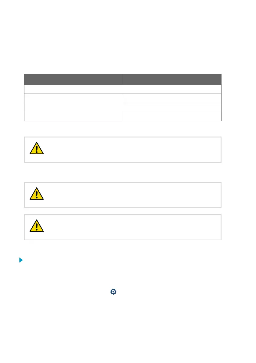
Table 4 Transmitter analog channel fixed test output levels
Current and voltage test output points Fixed test output level
Low point test output for current output 4 mA
High point test output for current output 20 mA
Low point test output for voltage output 1 V
High point test output for voltage output 10 V
For adjustment instructions, see Analog output adjustment example (page 44).
Always switch the Insight analog output adjustment mode o after
testing or adjusting to return the output to normal operating mode. Normal
measurement data output is not available in adjustment mode.
CAUTION!
7.4.1 Analog output adjustment example
Always switch o the transmitter power supply when connecting or
disconnecting screw terminal wiring. Do not energize the transmitter power
supply when wiring is not connected.
CAUTION!
Always switch the Insight analog output adjustment mode o after
testing or adjusting to return the output to normal operating mode. Normal
measurement data output is not available in adjustment mode.
CAUTION!
To test and adjust the voltage output level of analog output 1:
1. Switch o the transmitter power supply and open the transmitter cover.
2. Connect the multimeter wiring to analog output 1 screw terminals and close the
transmitter cover.
3. Power on the transmitter and connect the transmitter to Insight PC software.
4. To open the calibration menu, select
to access Insight main menu. In the main menu,
select Calibrate.
5. Select Analog output 1 and enable the adjustment mode with the Adjustment mode on/
o selection.
Indigo201 User Guide M212842EN-B
44
 Loading...


