6. Configuring relays
6.1 Relay configuration overview
Indigo200 transmitters have 2 configurable relays (relay A and relay B). Both relays have
configuration options for selecting the parameter that is used to control the relay, activation
triggers, hysteresis, and error state behavior.
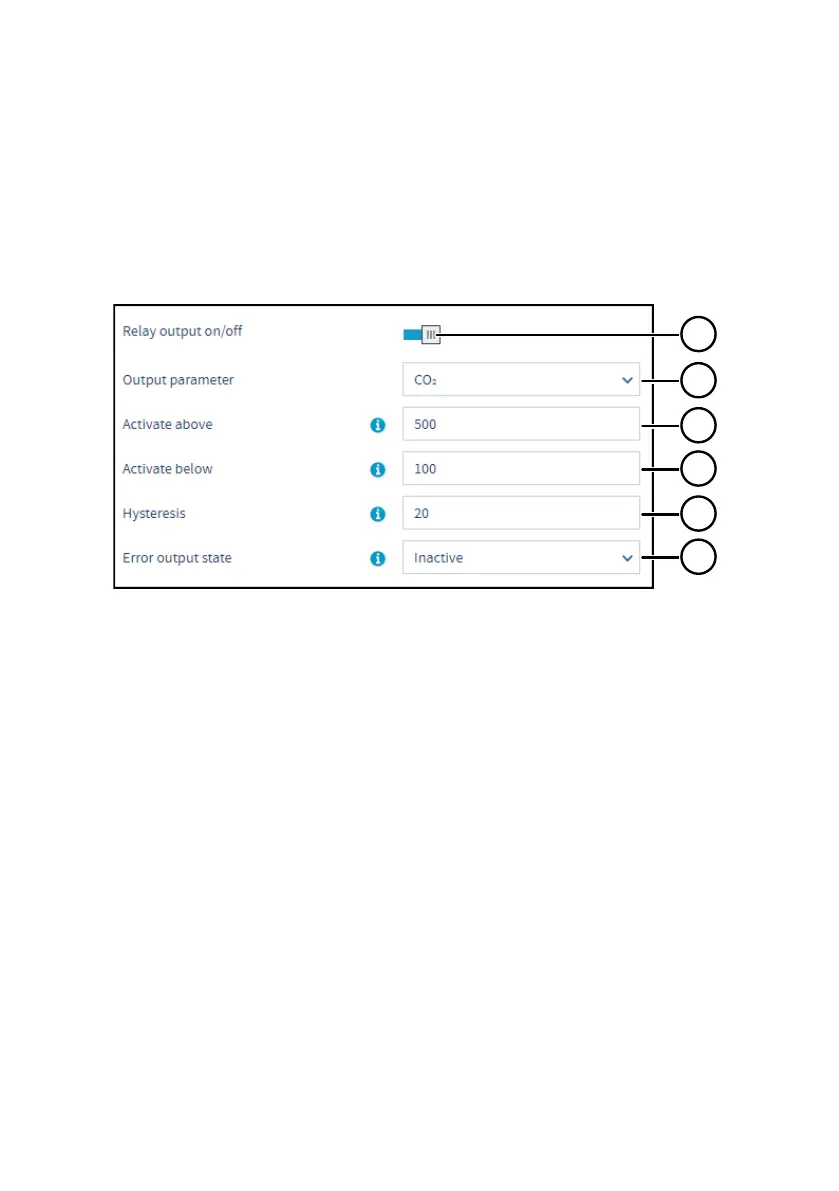
Figure 17 Relay configuration options (CO
2
probe example)
1 Relay output on/o: Set to ON to enable relay output.
2 Output parameter: The measurement that is used to control the relay. Options vary based
on the type of the connected probe.
3 Activate above:
When the measurement value exceeds the value set here, the relay activates.
See the dierent relay activation options described in Figure 20 (page 36).
4 Activate below:
When the measurement value falls below the value set here, the relay activates.
See the dierent relay activation options described in Figure 20 (page 36).
5 Hysteresis: Define a buer value for relay deactivation (set the value according to the
parameter selected for the relay). With hysteresis, an activated relay switches o only
when the measured value crosses the relay activation/deactivation limit and the additional
buer value.
6 Error output state: Select which state the relay is set to when an error occurs (on, o, or
remains in its current state).
Chapter 6 – Configuring relays
33
 Loading...


