VAMP 150
Motor protection relay
Operation and Configuration
VAMP Ltd
26
Vamp 24h support phone : +358 (0)20 753 3264
VM150.EN005
7. Commissioning configuration
7.1. Factory settings
When delivered from the factory, the relay has been given
factory default settings or settings defined by the customer.
The actual configuration can be read from the workshop test
reports or from the final test reports
7.1.1. Configuration during commissioning
The configuration and settings of the Motor protection relay
VAMP 150 is defined and checked during commissioning in
accordance with the instructions given in Chapter 5 of this
manual, for example in the following order:
1. Scaling of the rated values of the current transformer in
menu SCALING/IL Scale
2. Scaling of the rated values of the residual current
transformer SCALING/Io Scale
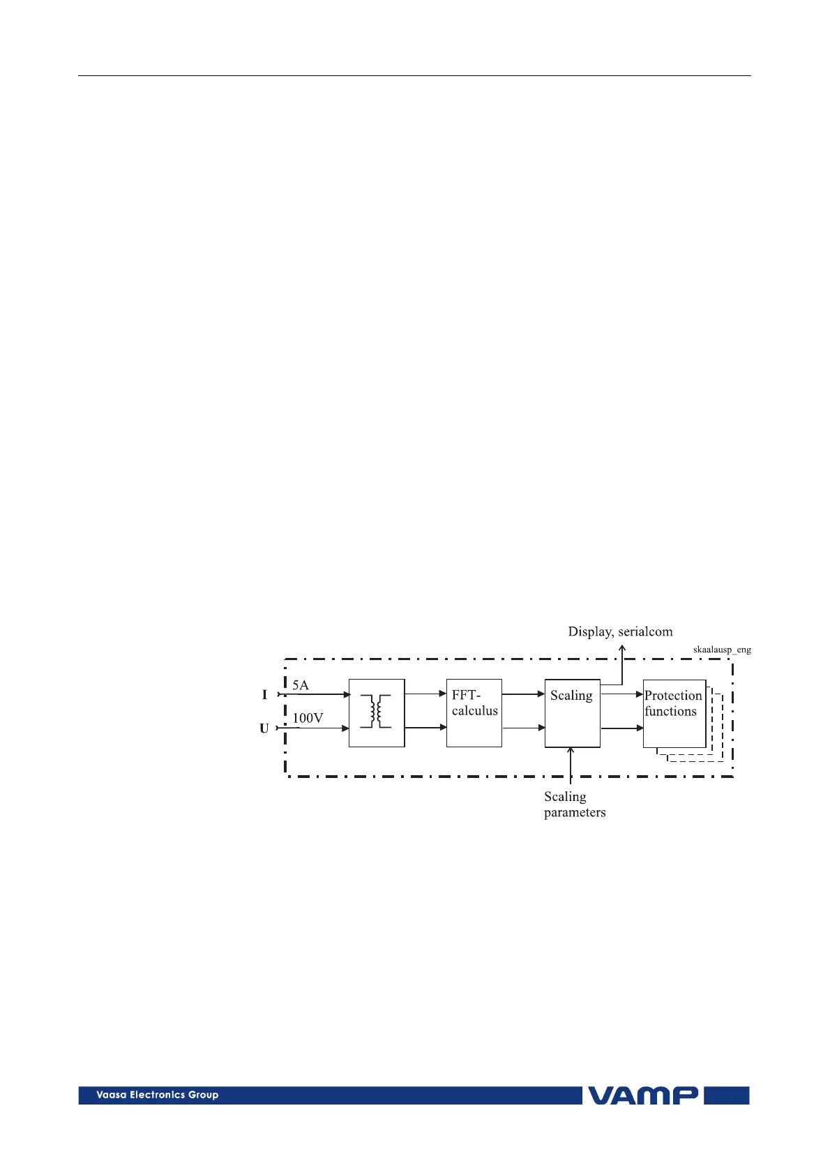
The scaling is done in the software block of the measured
signals, Figure 7.1.1-1. Thus the scaling affects all the
protection functions.
Figure 7.1.1-1 Principle for scaling the measured values of the VAMP 150
relay.
3. Activation of the desired protection functions, ENABLE
menu, see Chapter 5.2.
4. Setting values of the protection functions, IL SETTING and
Io SETTING menus, see Chapter 5.3.
5. Configuration of the starting and tripping signals of the
protection stages to the desired output relays and the LED
indicators (DOUT menu), see Chapter 5.5.
6.
Configuration of the blocking matrix (BLOCKING menu),
see Chapter 5.6.