VAMP 150 Motor protection relay
Technical Description
VAMP Ltd
16
Vamp 24h support phone : +358 (0)20 753 3264
VM150.EN005
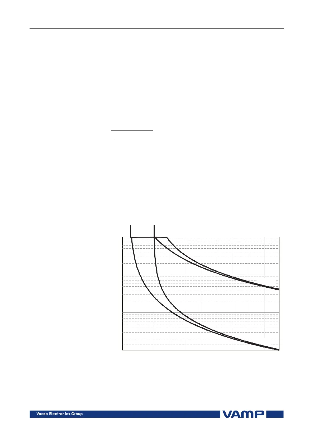
2.2.4. Unbalance protection I2> (46)
The unbalance stage protects the motor against unbalanced
phase currents and single phasing. The protection is based on
the negative sequence current.
Both definite time and inverse time characteristics are
available. The inverse delay is based on equation 2.2.4.-1. Only
the base frequency components of the phase currents are used
to calculate the negative sequence value I
2
.
Equation 2.2.4.-1
2
2
2
2
1
)( K
I
I
K
T
MOT
−
=
where,
T = Operation time
K
1
= Thermal time constant of the rotor (I
2
2
t value)
I
2
= Negative sequence phase current, base frequency
component
I
MOT
= Nominal current of the motor
K
2
= The maximum allowed degree of unbalance
0.1 0.2 0.4 0.4 0.5 0.6 0.7 0.8 0.9 1.0
I /I
2 MOT
10
1
100
1000
Operationtime(s)
K =40
1
K =0.2
2
K =0.05
2
K =0.2
2
K =0.2
2
K =0.05
2
K =0.05
2
K =1
1
Figure 2.2.4-1. Inverse operation delay of current unbalance stage I
2
>. The
longest delay is limited to 1000 seconds (=16min 40s).