VAMP Ltd
Motor protection relay
Technical Description
VAMP 150
VM150.EN005 Vamp 24h support phone : +358 (0)20 753 3264
7
2.2. Relay protection functions
2.2.1. Overcurrent protection I>, I>>, I>>> (50/51)
The three-phase overcurrent unit comprises three separately
adjustable overcurrent stages, i.e. stage I>, I>> and I>>>.
The overcurrent unit measures the fundamental frequency
component of the phase currents.
Stage I> can be configured for definite time or inverse time
operation characteristic. Stage I>> and stage I>>> have
definite time characteristic.
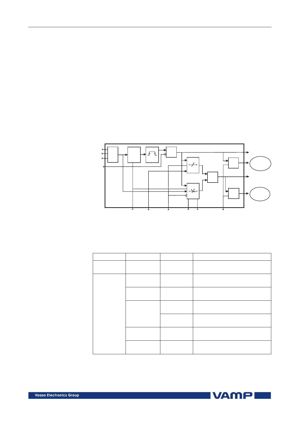
Figure 2.2.1-1 shows the functional block diagram of stage I>.
&
t
³1
&
&
>
ts
tr
MAX
3vIslohko
SettingI>s Delay Definite/inverse
time
EnableeventsInversetime
characteristics
Multiplier
Start
Trip
Register
event
Register
event
Im1
Im2
Im3
Block
Figure 2.2.1-1. Block diagram of the three-phase overcurrent stage I>.
Parameters of the overcurrent stages:
I>, I>>, I>>> (50/51)
I>, I>>, I>>> (50/51)I>, I>>, I>>> (50/51)
I>, I>>, I>>> (50/51)
Parameter
ParameterParameter
Parameter
Value/unit
Value/unitValue/unit
Value/unit
Measured
value
ILmax A Max. value of phase currents
IL1, IL2, IL3 primary values
I>, I>>,
I>>>
A Calculated setting value in
primary current units
I>, I>>,
I>>>
xImot Setting value as per unit value
DT Operation charact./ definite
time (I>)
Type
NI, VI
EI, LTI
Operation charact./ inverse
time (I>)
t>, t>>,
t>>>
s Operation time
Setting
values
k Time multiplier at inverse
time (I>)