VAMP 150 Motor protection relay
Technical Description
VAMP Ltd
26
Vamp 24h support phone : +358 (0)20 753 3264
VM150.EN005
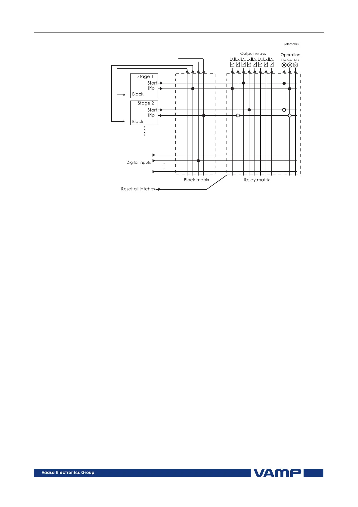
Figure 2.4-1. Operating principle of the grouping and blocking matrices.
2.4.1. Output relay matrix
By means of the relay matrix the output signals of the various
protection stages can be combined with the trip relay T1 and
T2, alarm relays A1...A3 and the operation indicator L1
(Alarm) and L2 (Trip).
When a connection is made, two functions can be selected, the
signal follower function (o) or the latching function (•), see
Figure 2.4-1.
The "Reset all latches" function resets all latched output relays
and operation indicators. The reset signal can be given via a
digital input, the key pad or the serial port. If the reset signal
is to be given via the digital input DI1, the Remote Release
(“RemRel”) input DI1 must be configured to function as a reset
input from DIGITAL IN/RemRel menu.
2.4.2. Blocking matrix
By means of the blocking matrix (Block matrix) the operation of
a protection stage can be blocked. The blocking signal can
originate from the digital input DI1, or it can be a start or trip
signal from a protection stage. In Figure 2.4-1, an active
blocking is indicated with a black dot ( • ) in the crossing point
of a blocking signal and a signal to be blocked.