VAMP Ltd
Motor protection relay
Technical Description
VAMP 150
VM150.EN005 Vamp 24h support phone : +358 (0)20 753 3264
13
2.2.3. Thermal overload stage T> (49M)
The overload stage measures the rms value of the phase
currents including harmonics up to 7th and calculates the
temperature dependent operation time according to the
equation 2.2.3.-1 (IEC 60255-8).
Equation 2.2.3.-1
MAX
P
II
II
T
22
22
ln
−
−
⋅=
τ
where,
T = Operation time. This is a result value.
τ = Thermal time constant of the motor. This is a base
value. The actual time constant depends of the status of
the stage (heating, cooling or stall). This is a setting
value.
I = The highest rms value of the three measured phase
currents. The rms value will include harmonics up to
7
th
. This is a measured value.
I
P
= Pre-load current corresponding to the present modelled
temperature. This is an internal calculated value.
I
MAX
= The maximum allowed continuous current
corresponding the maximum allowed temperature Θ
MAX
.
The temperature Θ
MAX
is the trip limit and also equals
the heat capacitance of the protected motor. The value
of I
MAX
is derived from overcurrent factor k, given
ambient temperature Θ
AMB
and parameters k
Θ40
and
k
Θ70
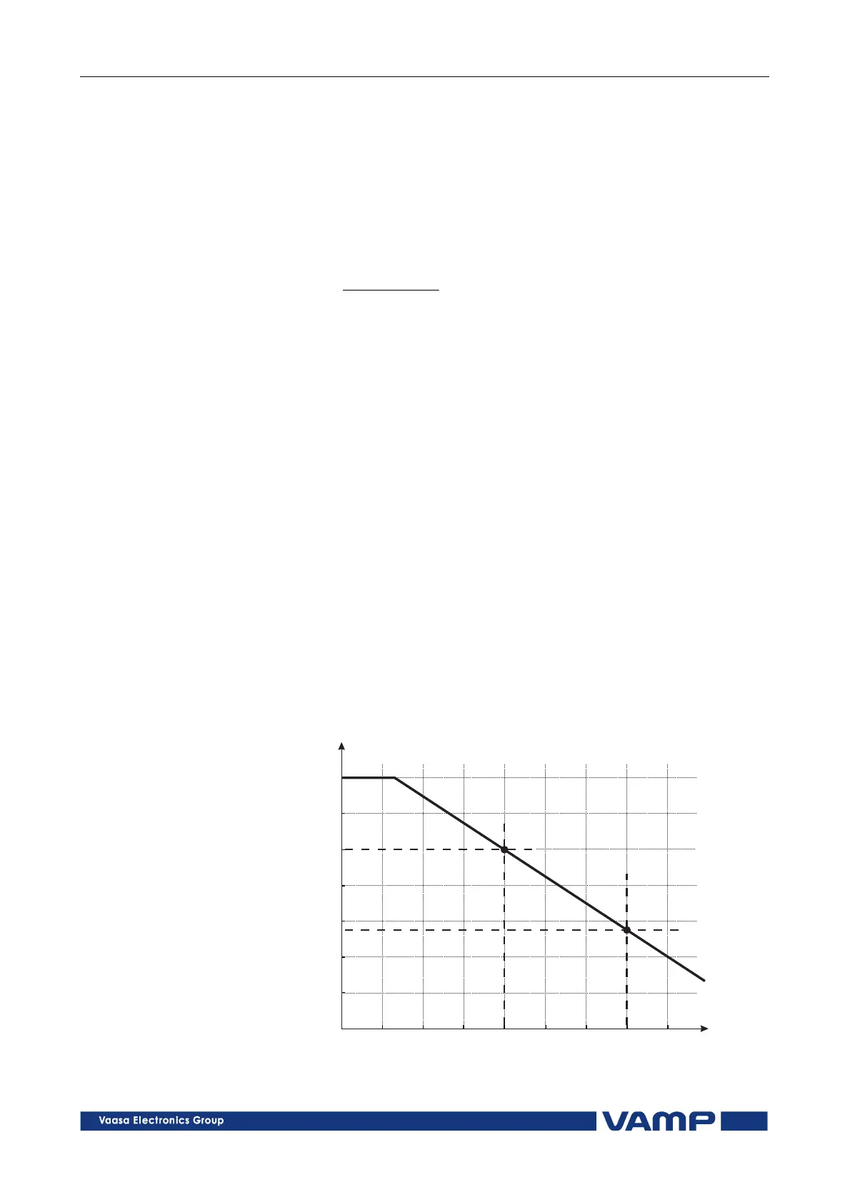
. See Figure 2.2.3-1.
20 30 50 7010
1.00
1.20
0.80
0.60
0.70
0.90
1.10
40 60 80
k
Q
(°C)Q
AMB
k
Q40
k
Q70
Figure 2.2.3-1. Ambient temperature correction of the overload stage T>.