VAMP Ltd
Motor protection relay
Operation and Configuration
VAMP 150
VM150.EN005 Vamp 24h support phone : +358 (0)20 753 3264
7
2. User interface
2.1. General
The VAMP 150 relay can be controlled in three ways:
•
Locally with the push-buttons on the relay front panel
•
Locally with a PC connected to the serial port on the relay
front panel
•
Via remote control over the remote control port on the relay
rear panel.
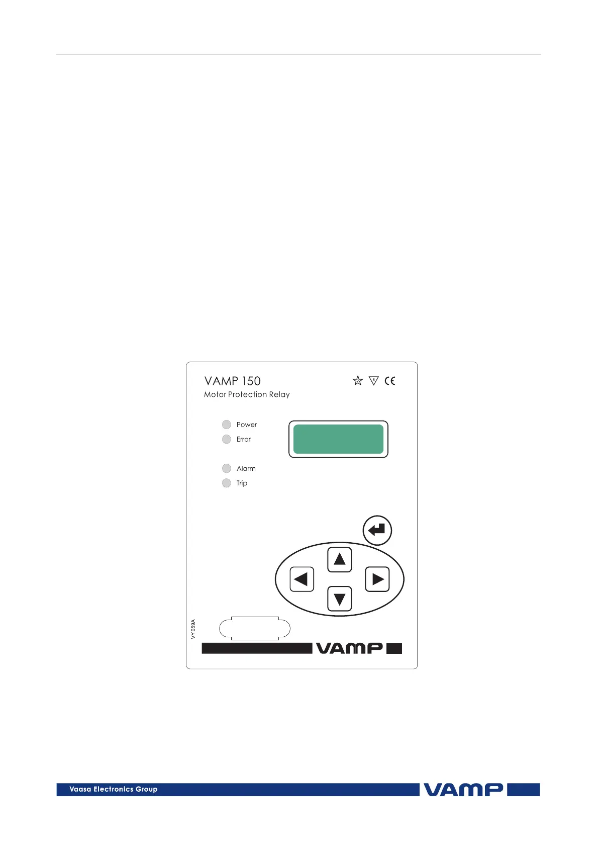
2.2. Local panel
Figure 2.2-1 below shows the location of the components of the
local user interface on the front panel of the relay.
Figure 2.2-1 Relay front panel.
1. Alpha-numerical LED display
2. Key pad
3. LED indicators
4.
RS 232 serial communication port for a PC