VAMP Ltd
Motor protection relay
Operation and Configuration
VAMP 150
VM150.EN005 Vamp 24h support phone : +358 (0)20 753 3264
9
Key functions
Function:
Function:Function:
Function:
Key:
Key:Key:
Key:
Note:
Note:Note:
Note:
Navigation downwards in the menu. Decreasing
of setting value/selection of text value in the
setting state
DOWN
Navigation upwards in the menu. Increasing of
number value/selection of text value in the setting
state
UP
Moving to the right in the menu (to submenu, to
parameter). Moving to the right in an adjustable
value, digit by digit
RIGHT
Moving to the left in the menu (to submenu /
main menu). Moving to the left in an adjustable
value, digit by digit
LEFT
Cancellation of change LEFT push > 2 s
Transfer of parameter into the setting state.
Activation of password supply and acceptance of
password while moving to the setting state.
Saving of setting and exit from setting state.
Resetting of alarm display in normal operating
state (USER level).
ENTER
Resetting of (LED) indicators ENTER
2.2.3. Indicators
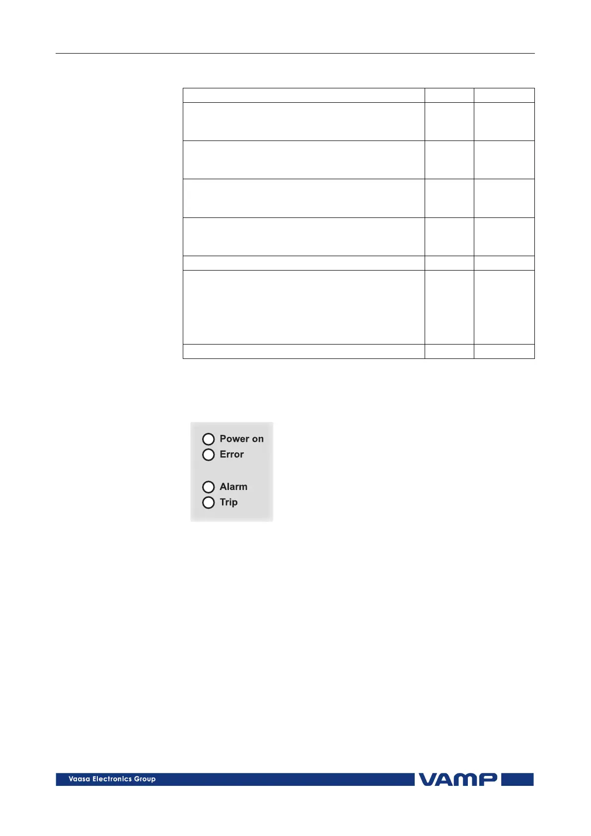
The relay front panel holds 4 LED indicators:
Figure 2.2.3-1 Relay operation indicators.
Relay operation indicators:
Power on
Power onPower on
Power on
auxiliary voltage switched on
Error
ErrorError
Error
self-supervision fault, the self-supervision output relay
operates in parallel with the indicator
Alarm
AlarmAlarm
Alarm
starting of protection stage
Trip
TripTrip
Trip
tripping of protection stage