VAMP Ltd
Motor protection relay
Technical Description
VAMP 150
VM150.EN005 Vamp 24h support phone : +358 (0)20 753 3264
23
&
&
Io
MAX
Ioarcset
>
Register
events
Trip
Enableevents
Setting
ArcIo>
L1>
L2>
ArcBI
>
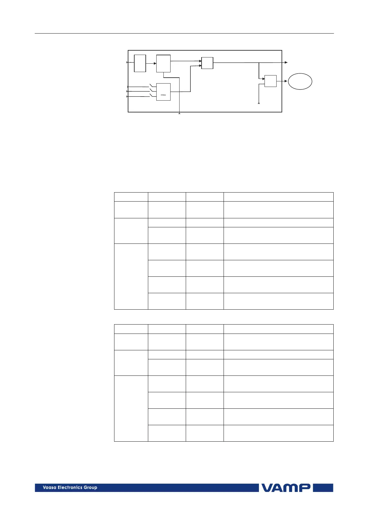
Figure 2.2.9-2. Block diagram of the arc protection stage ArcIo>. The symbol
of the starting of the arc sensor is L> and that of the fast earth-fault stage is
ArcIo.
The setting of the earth-fault arc protection stage is performed
in the menu called Io SETTING/ArcIo Set.
Parameters of the arc protection stage ArcI> (51L>):
Parameter:
Parameter:Parameter:
Parameter:
Value/unit:
Value/unit:Value/unit:
Value/unit:
Measured
value
IL max A Max. value of phase currents IL1,
IL2, IL3 primary values
ArcI> pu Setting value as per times In Setting
values
ArcI>
sensor
Selection of the arc sensor
channel(s) and/or arc binary input
SCntr Cumulative start counter, only
selected ArcCn arc activations
TCntr Cumulative trip counter, only
selected ArcCn arc activations
Flt % Maximum value of fault current as
per times In
Recorded
values
EDly % Elapsed time as compared to the set
operating time, 100%=tripping
Parameters of the arc protection stages ArcIo> (51NL>):
Parameter:
Parameter:Parameter:
Parameter:
Value/unit:
Value/unit:Value/unit:
Value/unit:
Measured
value
Io A Max. value of earth-fault current Io
primary value
ArcI> pu Setting value as per times Ion Setting
values
ArcI>
sensor
Selection of the arc sensor
channel(s) and/or arc binary input
SCntr Cumulative start counter, only
selected ArcCn arc activations
TCntr Cumulative trip counter, only
selected ArcCn arc activations
Flt % Maximum value of fault current as
per times Ion
Recorded
values
EDly % Elapsed time as compared to the set
operating time, 100%=tripping