Technical description 2 Protection functions 2.9 Stall protection Ist>
48
VM50.EN004 VAMP 24h support phone +358 (0)20 753 3264
59
The stall protection stage protects the motor against prolonged
starts caused by e.g. a stalled rotor. The pick-up setting I
st
> is
the current detection level for a motor start. While the current
has been less than 10% of I
mot
and then within 200 milliseconds
exceeds I
st
>, the stall protection stage starts to count the
operation time T according to Equation 2.9-1. The equation is
also drawn in Figure 2.9-1. When current drops below 120 % x
I
mot
the stall protection stage releases.
Equation 2.9-1
start
meas
start
T
I
I
T
, where
T = Operation time
I
start
=
Start current of the motor. Default 6.00xI
mot
I
meas
= Measured current during start
T
start
= Maximum allowed start time for the motor
TIME
CURRENT
I
START
T
START
IstartMin
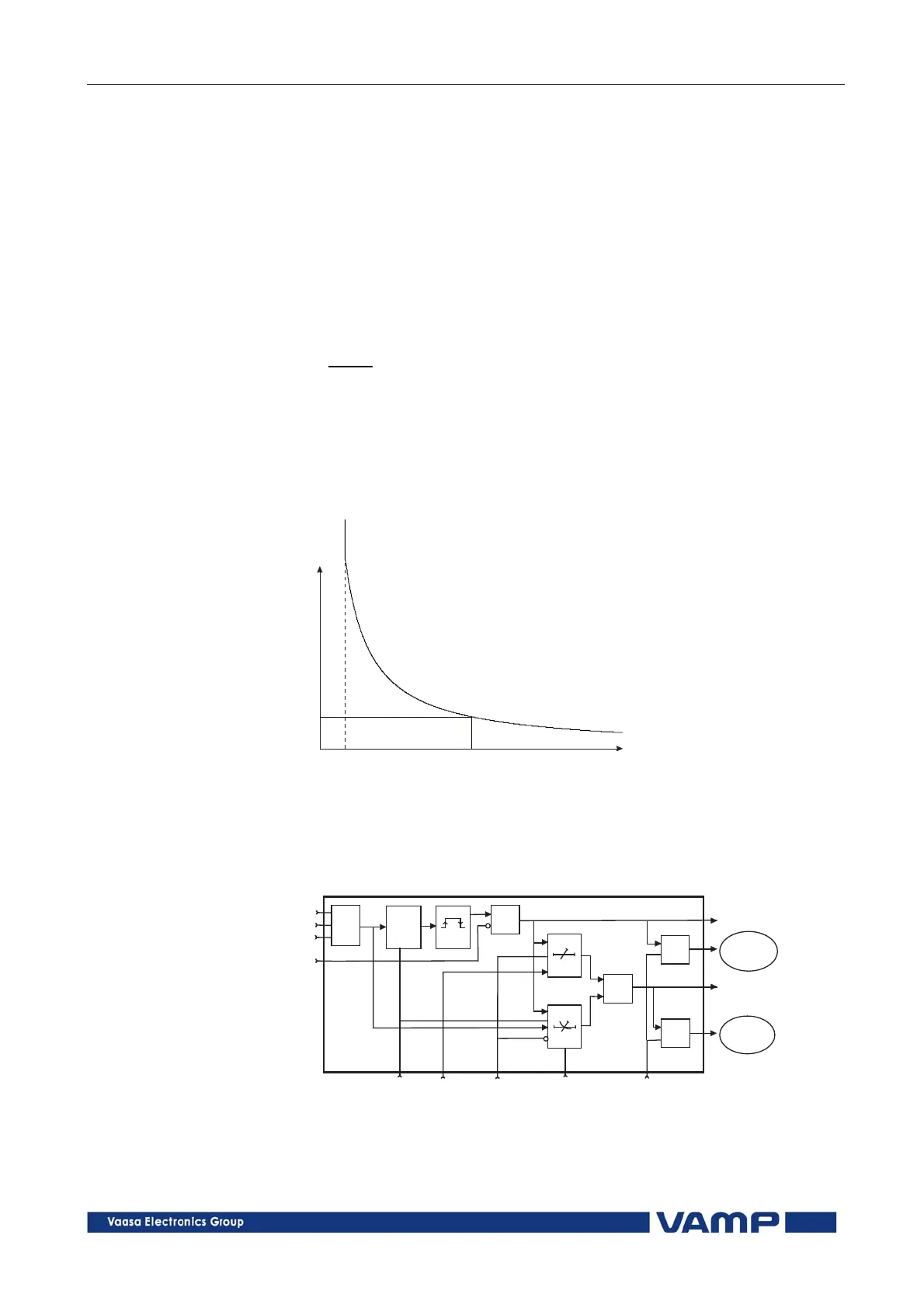
Figure 2.9-1 Operation time delay of the stall protection stage I
st
>.
If the measured current is less than the specified start current
I
start
the operation time will be longer than the specified start
time T
start
and vice versa.
&
t
&
&
>
t
s
t
r
MAX
Istlohko
Motor nom.
start current
Delay Definite / inverse
time
Enable events
Inverse delay
Start
Trip
Register
event
Register
event
Im1
Im2
Im3
Block
Figure 2.9-2 Block diagram of the stall protection stage I
st
>.