VCC 112, index H
AutoLift
TM
M3/M7 and M4/M8 lock
State of the lid limit switches
112 Left side
Lid S10 S11
UP position
1 0
AutoLift
TM
DOWN
(No feedback of info)
0 0
CLOSED position
(Pressure unit only)
0 1
112 Right side
Lid S12 S13
UP position
1 0
AutoLift
TM
DOWN
(No feedback of info)
0 0
CLOSED position
(Pressure unit only)
0 1
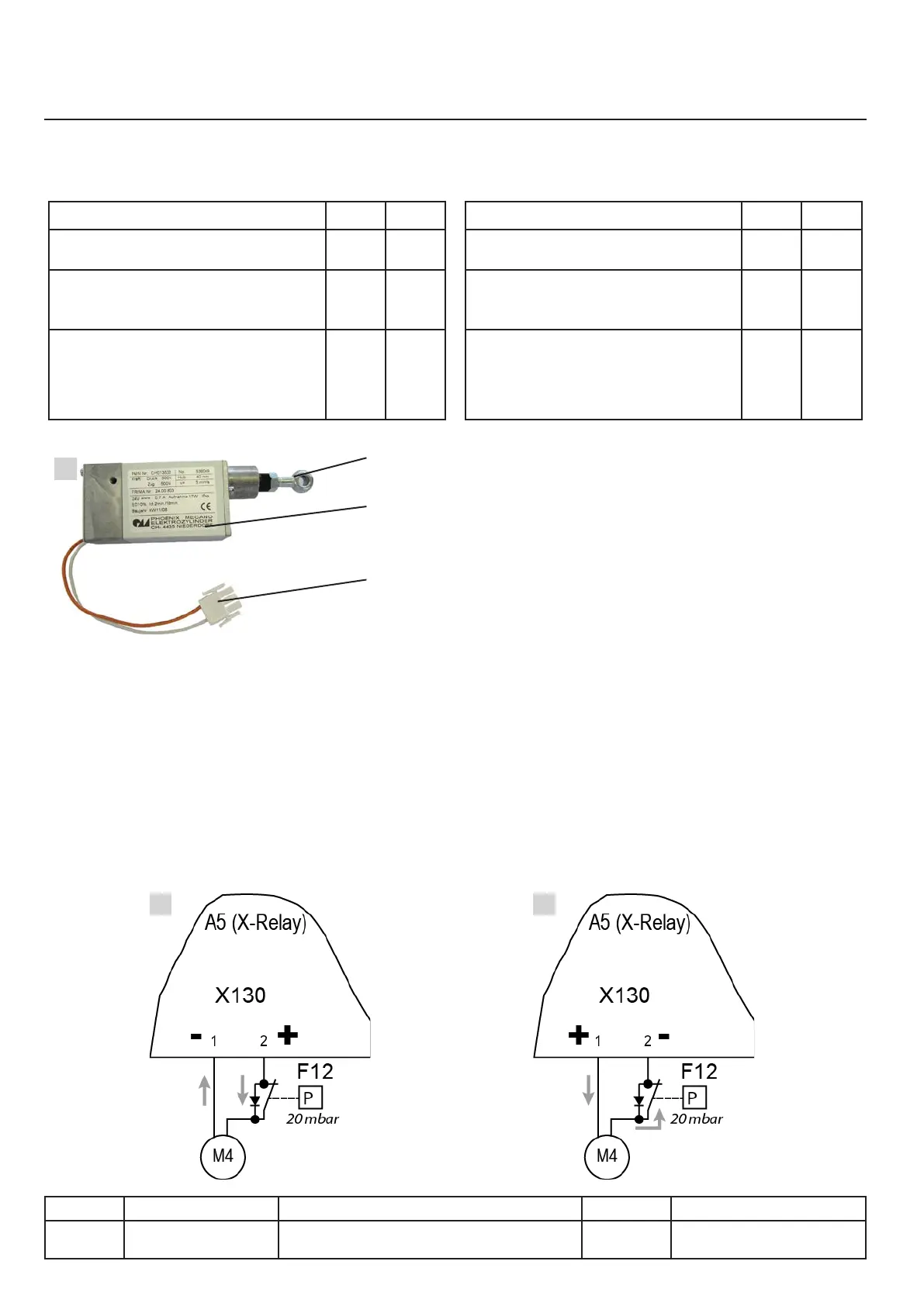
Actuator 24VDC Fig.1
A. Actuator rod
B. Mechanism with motor 24 VDC
C. Connectors for power supply 24 VDC
No internal limit switches to inform electronics. Only the
up position of the AutoLift is recognised by S10 / S12
Lock the lid on pressure equipment.
Role of the pressure switch F12/F13
Locking Fig.2
The F12 pressure switch (or F13 for the right
pan) has no effect, as it is bypassed by the
diode.
Example Fig. 2 and 3: Actuator left lid
Unlocking Fig.3
The power to the actuator for unlocking must
go through the pressure switch F12 (or F13)
for the right pan!
X.22
v03 • July-2016 • Hen
Motorisation Module
Line Units Serial number (starting from) Sw Revision
VCCM
VCCWE
112 E11xH1009xxxxxxx
A
B
C
2
1
3