Fluid flow is sensed and reported to the unit control by an ultrasonic flow sensor. The sensor is clamped to the unit piping
without penetrating the pipe or obstructing the flow.
To replace the flow sensor:
1. Shut off all power to the unit by opening the main disconnect switch on the electrical panel on the front of the
Vertiv™ CoolPhase CDU.
2. Open the display door and the high voltage deadfront.
3. Remove the front panel by turning the quarter turn latches located in the top two corners of the panel, and lifting
it up off the tabs in the base.
4. Disconnect the flow sensor cable.
5. Unscrew the two sensor mounting screws and remove the sensor.
6. Attach the new flow sensor to the mounting bracket with the two screws. Tighten screws evenly to ensure even
pressure on the rubber backing of the flow meter.
NOTE: Do not adjust the flow sensor location once the rubber backing has made contact with the pipe. The rubber
may tear, causing the flow sensor to not work properly.
7. Attach the sensor cable to the new flow sensor.
8. Replace the electric panel deadfront and restore power to the unit.
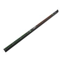
9. Program the flow sensor parameters using the instructions provided with the sensor. (See Figure 12.1 on the
facing page .)
10. Shut off all power to the unit by opening the main disconnect switch on the electrical panel on the front of the
CoolPhase CDU.
11. Slide the front panel over the tabs at the base, and hold in place by turning the quarter turn latches located in the
top two corners of the panel.
12. Close the high voltage deadfront and display door, fastening it in place with the quarter turn latches.
13. Restore power to the unit and close the display door.
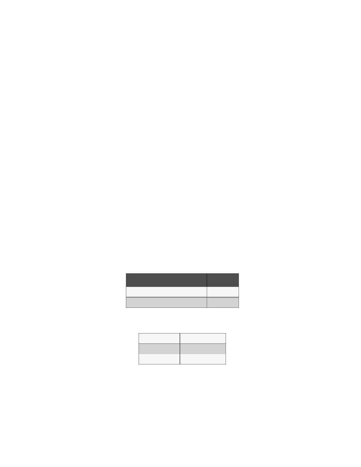
Parameter Setting Value
Analog output lower limit (A-LOF) 0 gpm
Analog output upper limit (A-HIF) 202 gpm
Table 12.3 Parameter Settings
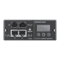
CH.2 ANLG
GAL ON
PIPE 2
Table 12.4 Initial Parameter Settings
98 Proprietary and Confidential ©2024 Vertiv Group Corp. 12 Maintenance
Vertiv™ CoolPhase CDU Installer/User Guide