8.3 Electrical Field Connections
The electrical connections are described in the submittal documents included in Table 8.1 below .
The following table lists the relevant documents by number and title.
Document Number Title
20000062 Vertiv™ Liebert® XDM Electrical Field Connections Liebert® XDM Models
DPN005140
Liebert® CoolPhase CDU CANbus and Interlock Connections Vertiv™ Liebert® MCV + Vertiv™ Liebert® EconoPhase + Base
Assembly
DPN005241 CoolPhase CDU and Liebert® XDM Electrical Data
Table 8.1 Electrical Field Connection Drawings
8.4 Wiring the Upper Section to the Bottom Module
The electrical connections between the upper and lower module need to be completed.
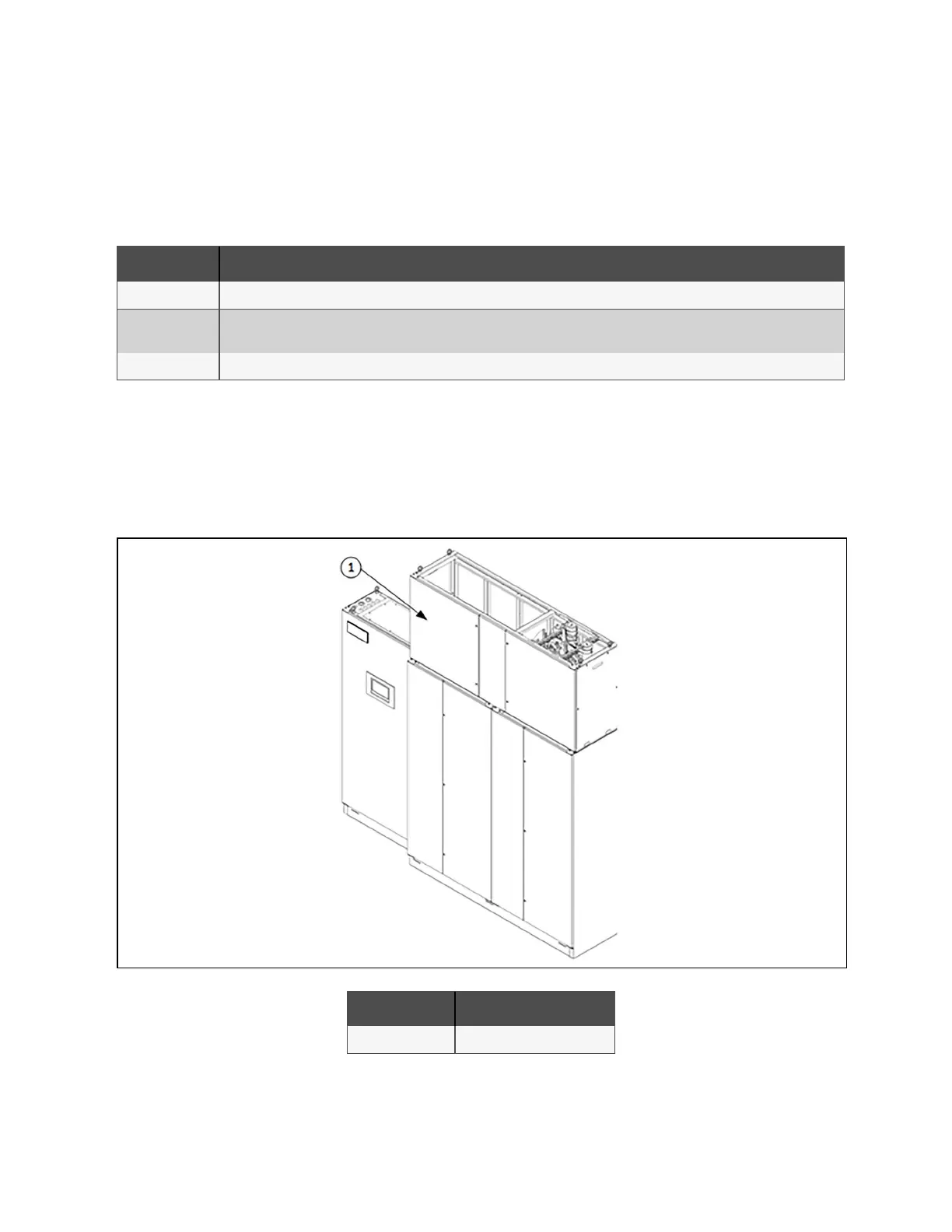
1. Open front door on the top model shown in Figure 8.1 below .
Figure 8.1 CoolPhase CDU Front Door
Item Description
1 Front Door
2. The cables for the VFD pump are coiled up and cabled tied to the internal frame of the top module, shown in
Figure 8.2 on the next page .
8 Electrical Connections Proprietary and Confidential ©2024 Vertiv Group Corp. 81
Vertiv™ CoolPhase CDU Installer/User Guide