3 Pre-installation Preparation and Guidelines
NOTE: Before installing unit, determine whether any building alterations are required to run piping, wiring, and duct
work. Follow all unit dimensional drawings and refer to the submittal engineering dimensional drawings of individual
units for proper clearances.
Refer to Model Number Nomenclature on page9 and the appropriate submittal drawings to determine the type of system
being installed and anticipate building alterations, piping, and duct work needed.
The unit dimensions, pipe connection locations, and piping schematics are described in the submittal documents included in
the Submittal Drawings on page107 .
For initial start-up runtime of the customer fluid loop, consider the options listed in Table 3.1 below , dependent upon the
situation.
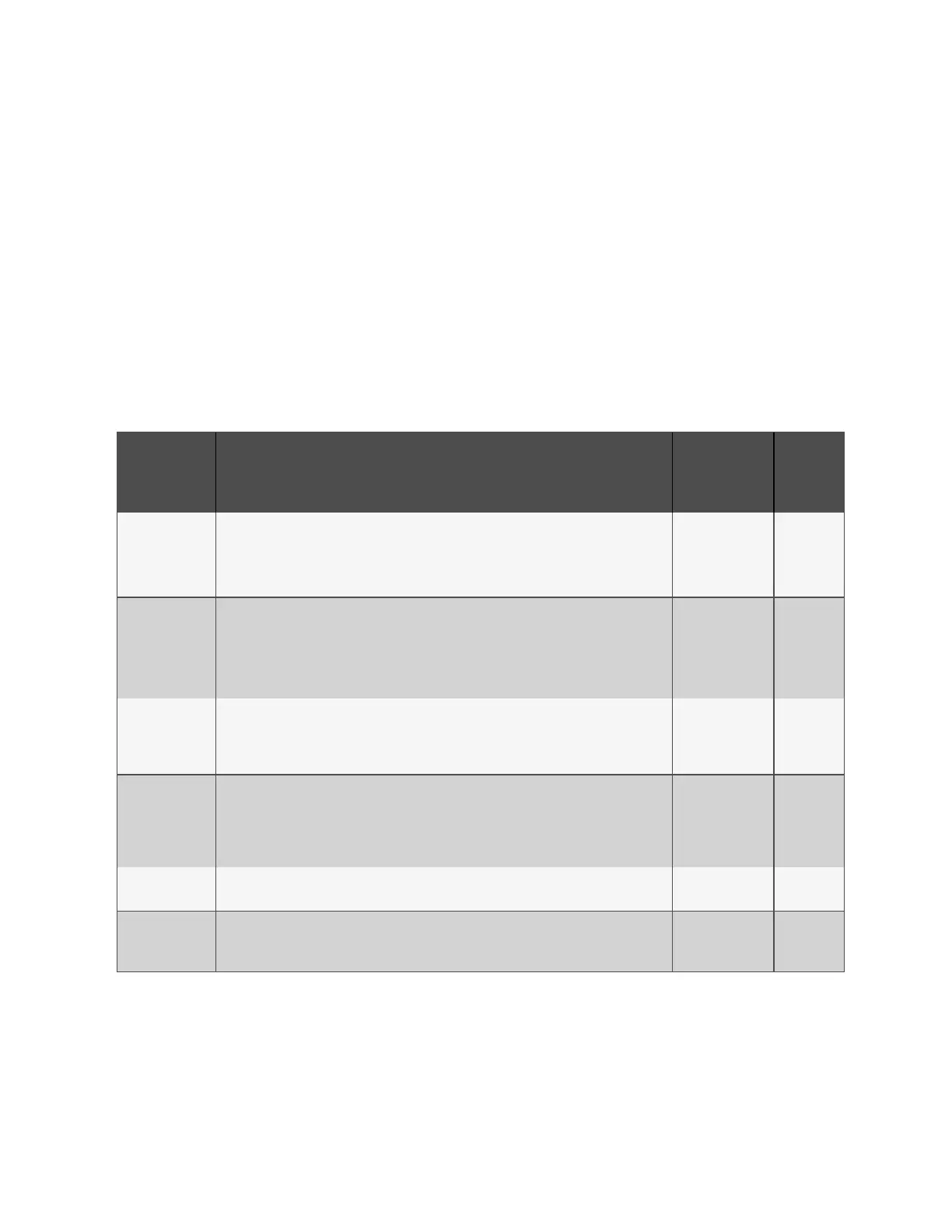
Option Detailed Explanation Requirement
Refer to
Figure 3.1
on the next
page
1. Filters and
strainers
Per customer requirements, there may be micron filters or additional strainers specified by the
customer or their consulting engineer, as a requirement for their unique application.
This requirement may be driven by an equipment supplier (e.g., liquid cooled servers or rack
mounted CDUs) or it may be best practices for the CW loop (to maintain water quality).
Follow CW loop
design by others.
A
2. Field provided
30-40 mesh
strainer at inlet of
CoolPhase CDU
This Y-strainer is required near the Vertiv™ CoolPhase CDU at the CW return line to prevent
debris or particulates from entering the CoolPhase CDU heat exchanger.
This is to reduce the likelihood of a flow blockage in the heat exchanger. The biggest culprit
may be construction debris so after initial operation, the strainer should no longer require
cleaning.
Always required
with Liebert®
CoolPhase CDU
installations.
B
3. Strainer or
micron filter at
cooling load
Heat exchangers with fine passages may need to be protected from construction debris. So a
filter or strainer should be provided to allow that debris to be caught and removed as part of the
initial fill and start-up operation. The rating of this filter or strainer will be specified by the heat
exchanger requirements.
Per heat
exchanger
manufacturer's
specifications.
C
4. Loop to flush
piping
Include a loop or bypass located at the branch locations to individual loads, to flush debris prior
to load connections.
Per in rack
manifold and cold
plate
manufacturer’s
specifications.
D
5. Bypass
arrangement
Field supplied and installed for rear door heat exchanger application where the fluid flow rate is
less than minimum recommendation.
Field supplied and
installed.
E
6. Auto-vent for
air in fluid loop
Long horizontal pipe runs and high points of fluid piping tend to trap air and make it hard for the
unit to run effectively. It is recommended to place automatic air vents in several places around
the loop for an easier start-up process.
Field supplied and
installed
F
Table 3.1 Initial Start-up Runtime Options for Customer Loop
3 Pre-installation Preparation and
Guidelines
Proprietary and Confidential ©2024 Vertiv Group Corp. 21
Vertiv™ CoolPhase CDU Installer/User Guide