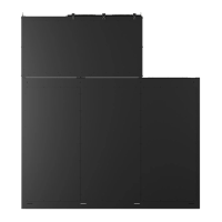
• The Vertiv™ CoolPhase CDU is used with a Vertiv™ Liebert® MCV heat rejection skid without receiver
tanks. For these systems, the bottom of the condenser coil cannot be more than 15 ft. (4.6 m) below the
elevation of the EEV inside the indoor units. The bottom of the condenser coil must be no greater than 60 ft. (18.3
m) higher than the elevation of the EEV inside the indoor unit. Refer to 20000101 included in Submittal Drawings
on page107 .
• Install traps on hot gas (discharge) lines at the base of vertical risers over 5 ft (1.5 m) and then for vertical rises
over 25 ft. (7.6 m), install a trap in 20 ft (6 m) increments or evenly-divided over the vertical rise.
• Pitch horizontal hot gas piping down at a minimum rate of 1/2 in. per 10 ft. (42 mm per 10 m) so that gravity will
aid in moving oil in the direction of refrigerant/oil flow.
• Consult factory if piping run exceeds 200 ft. (61 m) linear length or 300 ft. (91 m) equivalent length.
• Keep piping clean and dry, especially on units with R-410A refrigerant.
• Avoid piping runs through noise sensitive areas.
• Do not run piping directly in front of discharge air stream.
• Refrigerant oil—do not mix oil types.
• Refrigerant piping must be Type ACR copper pipe.
• Refrigerant connections to the unit must be high-temperature brazed joints. Do not use soft soldering.
• Field installed piping must be installed in accordance with local codes and must be properly assembled,
supported, isolated, and insulated.
Refer to ASHRAE Refrigeration Handbook for general, good-practice refrigeration piping. The indoor cooling unit has a
factory installed high pressure safety switch in the high side refrigerant circuit.
NOTE: All indoor and outdoor field refrigerant piping must be insulated 1/2 in., minimum. All outdoor insulation must
be UV and ozone resistant.
• Refer to Refrigerant Line Sizes and Equivalent Lengths on the next page , for recommended refrigerant piping
sizes based on equivalent pipe lengths.
• Refer to Refrigerant Charge Requirements for Air Cooled Systems on the next page for the refrigerant charge
requirements of the system.
• Refer to Charging the Refrigerant Circuit to an Outdoor Air Cooled Condenser without Receivers ( MCV430) on
page1 for more information.
5.3.2 Piping Layout and Condenser Positioning
The piping layout and condenser positioning is detailed in the submittal documents included in Submittal Drawings on
page107 .
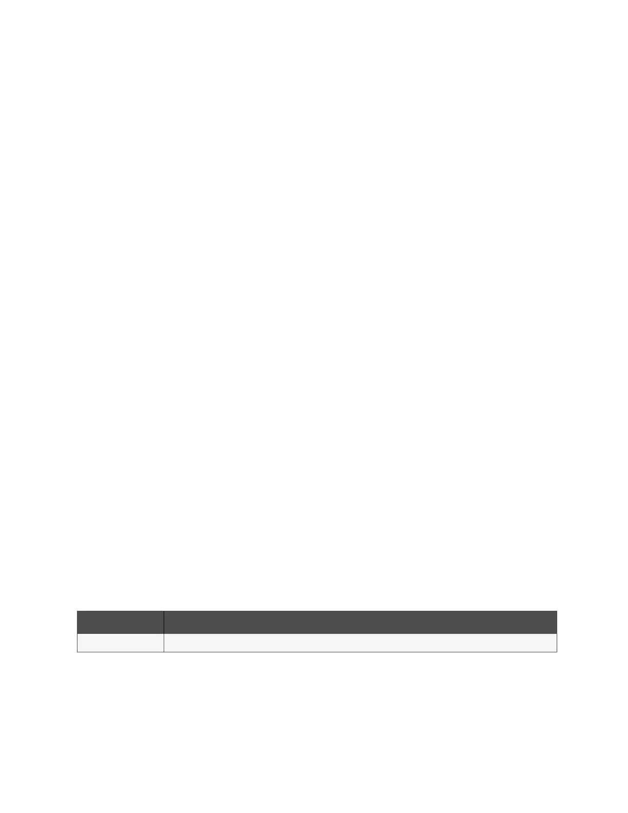
The following table lists the relevant documents by title and number.
Document Number Title
20000101 CoolPhase CDU Air Cooled Piping Schematic Vertiv™ Liebert® MCV Mounted above Liebert® XDM
Table 5.3 Refrigeration Piping Layout and Condenser Positioning Drawings
5 Refrigerant Piping Requirements Proprietary and Confidential ©2024 Vertiv Group Corp. 49
Vertiv™ CoolPhase CDU Installer/User Guide