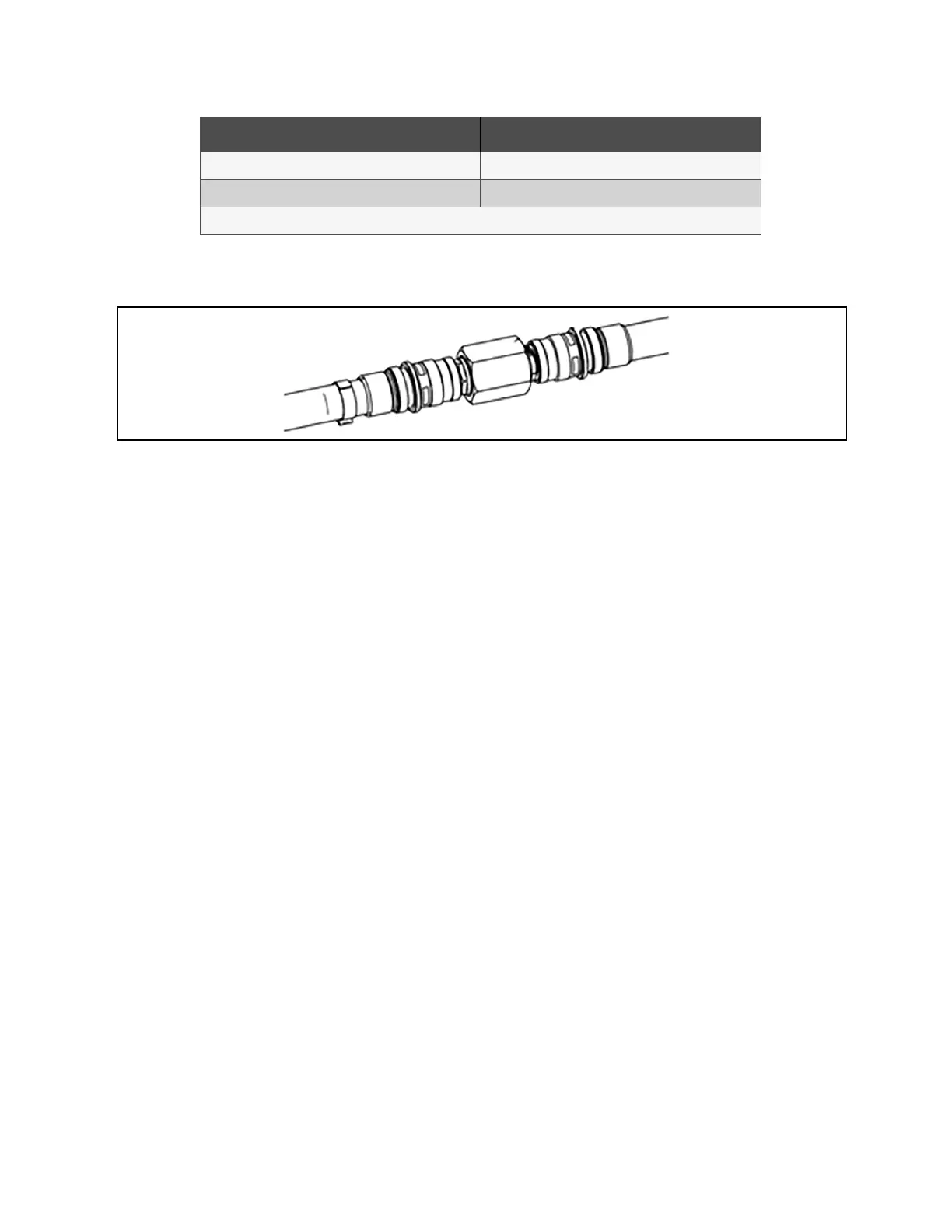
Item Description
1 Male Socket connect (Qty 2)
2 High pressure threaded straight (Qty 1)
NOTE: Engineer of record is responsible to make final determination regarding parts and arrangement.
9. Connect in-rack manifold supply and return to the bypass jumper assembly.
Figure 7.7 Example of Connecting In-Rack Manifold to Bypass Jumper Assembly
10. Verify that newly fitted secondary pipework and connections, including hoses have been tested for leaks.
11. Confirm connection of hoses to row manifold and racks are tight.
12. Run system with chilled water load banks. (This step is done without customer IT equipment.)
13. Leak check system.
NOTE: We recommend isolating the CoolPhase CDU unit with field installed shut off valves during leak checking of
field installed piping. When the units are included in a leak test, use of fluid for pressure testing is recommended.
When pressurized gas is used for leak testing the unit, the maximum recommended pressure is 30 psig (207 kPa) and
tightness of the unit would be verified by pressure decay over time (<2 psig/hour [13.8 kPa/hour]) or sensing a tracer
gas with suitable instrumentation. Dry seals in fluid valves and pumps may not hold a high gas pressure.
NOTICE
Risk of leaking fluid. Can cause equipment damage and serious building damage. Check the cooling fluid system
for leaks before commissioning. Check the fluid pipe connection to the heat exchanger and inspect the
mechanical condition of the cooling fluid circuit and connections thoroughly.
To check for leaks:
• Check that the secondary row manifold and drip tray have been installed in the correct location (if applicable).
• Confirm that the flow directions of field installed components are correct.
• Confirm that all isolating valves are open.
• Repair any leaks.
14. If no leaks are present, drain secondary fluid circuit and clean filters at the CoolPhase CDU.
15. Run the system loop at max design flow and periodically visually check the filters in the CoolPhase CDU for
contamination. Clean the filters before reintroducing them into the loop or system and continue cleaning the
loop until no contamination is present. The process of running the unit and checking the filters needs to be done
repeatedly until the engineer of record determines that it is appropriate to install the ITequipment.
16. Run at the max design flow rate.
76 Proprietary and Confidential ©2024 Vertiv Group Corp.
7 Secondary Fluid Circuit
Requirements
Vertiv™ CoolPhase CDU Installer/User Guide