Chapter 1 Installation Of UPS Rack System 8
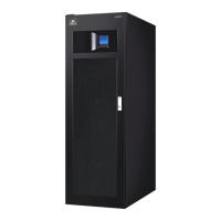
1.4.1 System Cabinet
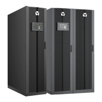
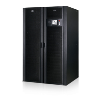
A UPS system can comprise an UPS rack system, external battery cabinet, depending on the specific system
requirement.
All the UPS system cabinets used in the same installation site are of the same height and should be positioned
side-by-side to achieve an aesthetically appealing effect.
Refer to
Chapter 7 Installation Drawing for the positioning of UPS cabinet.
1.4.2 Mooving The Cabinets
Warning
Ensure that any lifting equipment used in moving the UPS cabinet has sufficient lifting capacity.
The UPS is fitted with castors – take care to prevent movement when unbolting the equipment from its shipping pallet. Ensure
adequate personnel and lifting aids are available when removing the shipping pallet.
Ensure that the UPS weight is within the weight loading capacity range of any hoisting equipment. See Tab.
1-1 for
UPS weight.
UPS and optional cabinets can be handled by means of a fork lift or similar equipment. The UPS cabinet can also be
moved by its castors when moving in a short distance.
Note: Care must be taken when handling units fitted with batteries. Keep such moves to a minimum.
1.4.3 Transporting The Cabinets
Note :
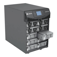
The unit can be shipped whit 1, 2 or 3 power modules installed but not with 4 or 5 ( to be ship separate), and cannot
be with any battery modules installed
1.4.4 Clearances Required For Operating
As LIEBERT APM series UPS has no ventilation grills at either sides, no clearances are required for the sides.
To enable routine tightening of power terminations within the UPS, it is recommended that clearance around the front
of the equipment should be sufficient to enable free passage of personnel with the doors fully opened. It is important
to leave a distance of 350mm in the rear side of the rack to permit adequate circulation of air coming out of the unit.
If the UPS make use of internal modular battery sufficient clearing shall be given at the back site to allow personnel to
operate the battery circuit breakers (~ 600mm)
1.4.5 Front Access
The component layout of the UPS rack system supports front access and repairing the UPS, thus reducing the space
requirement for side and rear access.
1.4.6 Final Positioning
When the equipment has been finally positioned, ensure the adjustable feet are set so that the UPS will remain
stationary and stable.
1.4.7 Installation Of Adjustable Feet
Installation diagrams in
Chapter 4 of this manual identify the location of the holes in the base plate through which
the equipment can be bolted to the floor. If the UPS is to be located on a raised floor, it should be mounted on a
pedestal suitably designed to accept the UPS point loading (more than 1000 kg). Refer to the bottom view in Fig.
4-7
to design this pedestal and stable.
 Loading...
