Chapter 2 Battery installation 17
LIEBERT APM UPS Module And Parallel System 30kVA~150kVA User Manual
12V
12V
GND
BIG
ENV
J7
Fig.
1-8:
Battery Input interface
Position Name Meaning
J7.1 ENV
3
Environmental alam detection (normally closed)
J7.2
BtG
1,2
Battery short to ground detection
J74 +12V +12V power supply
Note:
1. Must be configured by configuration software before becoming active.
2. Activating this feature turns the battery charger off
Tab.
1-7: Description of dry contact input port
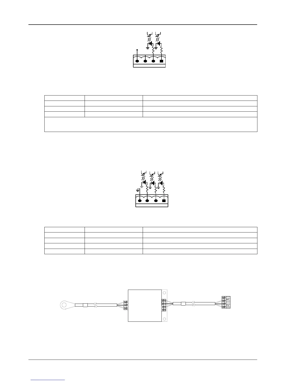
1.7.5 Battery temperature sensor Interface (J8)
The input dry contact port J8 is ment to be connected to the battery temperature sensor (TMP-2) provided as an
option with the UPS. The connection of the battery temperature sensor is shown in Figure 1-12.
GND
BAT-OUT
+12V
BAT-IN
J8
Position Name Meaning
J8.1 TMP_BAT_IN
Internal battery temperature detection
J8.2 +12V_A +12V power supply
J8.3 TMP_BAT_OUT External battery temperature detection
J8.4 GND_A Power supply GND
The external battery temperature sensor (option) is composed of a temperature probe and a temperature
transmission board, as shown in Error! Reference source not found.. The battery temperature sensor is connected
to the UPS monitoring board. When it is connected to the UPS, UPS will automatically detect the device and make
compensate according to the temperature of battery.
TMP-2
To J8 on UPS bypass module
To battery sensing point
4
3
2
1
1
2
3
4
Fig.
1-9 Battery temperature sensor
Q1:+12V, GND, BAT-IN are for internal battery temperature sensor.
Q2:+12, GND, BAT-OUT are for external battery temperature sensor,