Chapter 1 Installation Of UPS Rack System 14
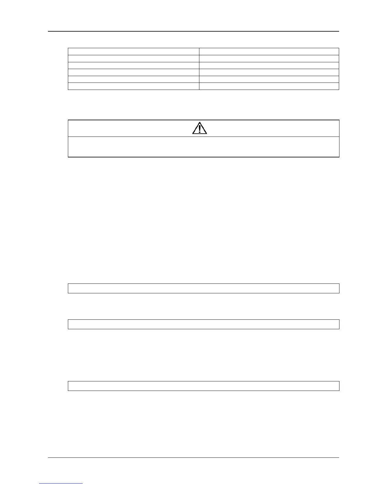
UPS 150kVA UPS minimum distance to floor(mm)
Rectifier AC input bus 203
Bypass AC input bus 203
UPS AC output 200
Battery input bus 256
Auxiliary cables: Connected to monitoring board (U2) 1850
Tab.
1-4: Distances from floor to connection points
1.6.1 Cable Connections
Note
The operations described in this section must be performed by authorized electricians or qualified technical personnel.. If you have
any difficulties, do not hesitate to contact our Customer Service & Support department at the address given at the beginning of this
manual.
After the equipment has been finally positioned and secured, refer to
Chapter 4 Installation Drawing to connect the
power cables as described in the following procedures:
1. Verify that all the external input distribution switches of the UPS are completely opened and the UPS internal
maintenance bypass switch is opened. Attach necessary warning signs to these switches to prevent unauthorized
operation.
2. Open the doors of the UPS, remove the front protective cover and then the power connection buses are visible.
3. Connect the protective earth and any necessary grounding cables to the enclosure of the cabinet at the bottom
part of the UPS rack (close to the cabinet side where the output connection terminal strips are located).The cabinet
for the UPS must be connected to the user’s ground connection.
Note: The grounding cable and neutral cable must be connected in accordance with local and national codes
practice.
Referring to
Fig.
4-11
, Identify and make power connections for incoming cables according to one of the procedures below,
depending on the type of installation:
Common Input Connections
4. For common bypass and rectifier inputs, connect the AC input supply cables to the UPS input terminals
(mA-mB-mC-mN) ensuring correct phase rotation. Tighten M6 bolts to 5 Nm.
Split Bypass Connections
5. If a 'split-bypass' configuration is used, connect the AC input supply cables to the rectifier input terminals
(mA-mB-mC-mN) and the AC bypass supply cables to the bypass input terminals (bA-bB-bC-bN) ensuring correct
phase rotation. Tighten M6 bolts to 5 Nm
Note: For split Bypass operation ensure that the busbars between Bypass and Rectifier inputs are removed. The
neutral line of bypass input must be connected to that of the rectifier input.
Frequency Converter Mode
If the frequency converter configuration is used, connect the AC input cables to the rectifier input terminals
(mA-mB-mC-mN) ensuring correct phase rotation. Tighten M6 bolt to 5Nm, M8 bolt to13Nm and M10 bolt 26Nm.
No need to connect the bypass input cables to bypass input terminals (bA-bB-bC-bN).
Note: For the frequency converter operation mode, ensure that the busbars between Bypass and Rectifier inputs are
removed.